System and method for overlaying color cues on a virtual representation of an anatomical structure

a virtual representation and color cue technology, applied in image analysis, image enhancement, instruments, etc., can solve the problems of uncontrollable growth of abnormal cells, detection of internal defects in objects, and cancerous growth forms, so as to enhance the features of virtual dissection and fast and easy identification

Active Publication Date: 2012-04-24
GE MEDICAL SYST GLOBAL TECH CO LLC
View PDF12 Cites 10 Cited by
  • Summary
  • Abstract
  • Description
  • Claims
  • Application Information

AI Technical Summary

Benefits of technology

[0016]The system and method of the invention allows portions of a virtually dissected colon to be highlighted on a display. Highlighting may allow a user to identify various structures of the virtual dissection for faster and easier identification. For example, a particular application of an embodiment of the invention may be used to instruct the display unit to display the virtual dissection of a colon created from three dimensional CT data. Then a user may instruct the display unit to display the shape information of the colon. The shape information may be highlighted to enhance the features of the virtual dissection. Also, a user may, instruct the display unit to highlight any liquid in the colon. Similarly, a user may instruct the display unit to display any contrast enhanced fecal matter in the colon, for example. Such improvements in CT examination capabilities increase the possibility of using a CT examination for large scale screening for colonic polyps, and other identification operations, for example.

Problems solved by technology

For instance, internal defects in an object may be detected.
Although there are many different kinds of cancer, they all share a common cause: an uncontrollable growth of abnormal cells.
Not all forms of cancerous growths, however, are easily detected using tomographic reconstruction.
Colonic polyps develop slowly and may take years before becoming cancerous.
Currently, however, it is difficult to identify potentially cancerous polyps in a virtually dissected view.
Hence, cancerous polyps may “blend in” with the background folds and structures of the lumen, causing the polyps to go undetected.
Also, a user may not be aware of excess liquid or fecal matter that may be concealing a cancerous polyp.
The lack of visual cues in current systems may cause potentially cancerous polyps to go undetected.
Moreover, the time required to interpret a virtually dissected view is typically long due to the fact that such analysis is done by a human observer.
A human is naturally susceptible to error, and inspections may yield false negatives or false positives, resulting in misdiagnosis or unnecessary surgery.
Even correct diagnosis is typically long due to the manual, imprecise nature of the analysis.

Method used


Image

  • System and method for overlaying color cues on a virtual representation of an anatomical structure
  • System and method for overlaying color cues on a virtual representation of an anatomical structure
  • System and method for overlaying color cues on a virtual representation of an anatomical structure

Examples


Embodiment Construction

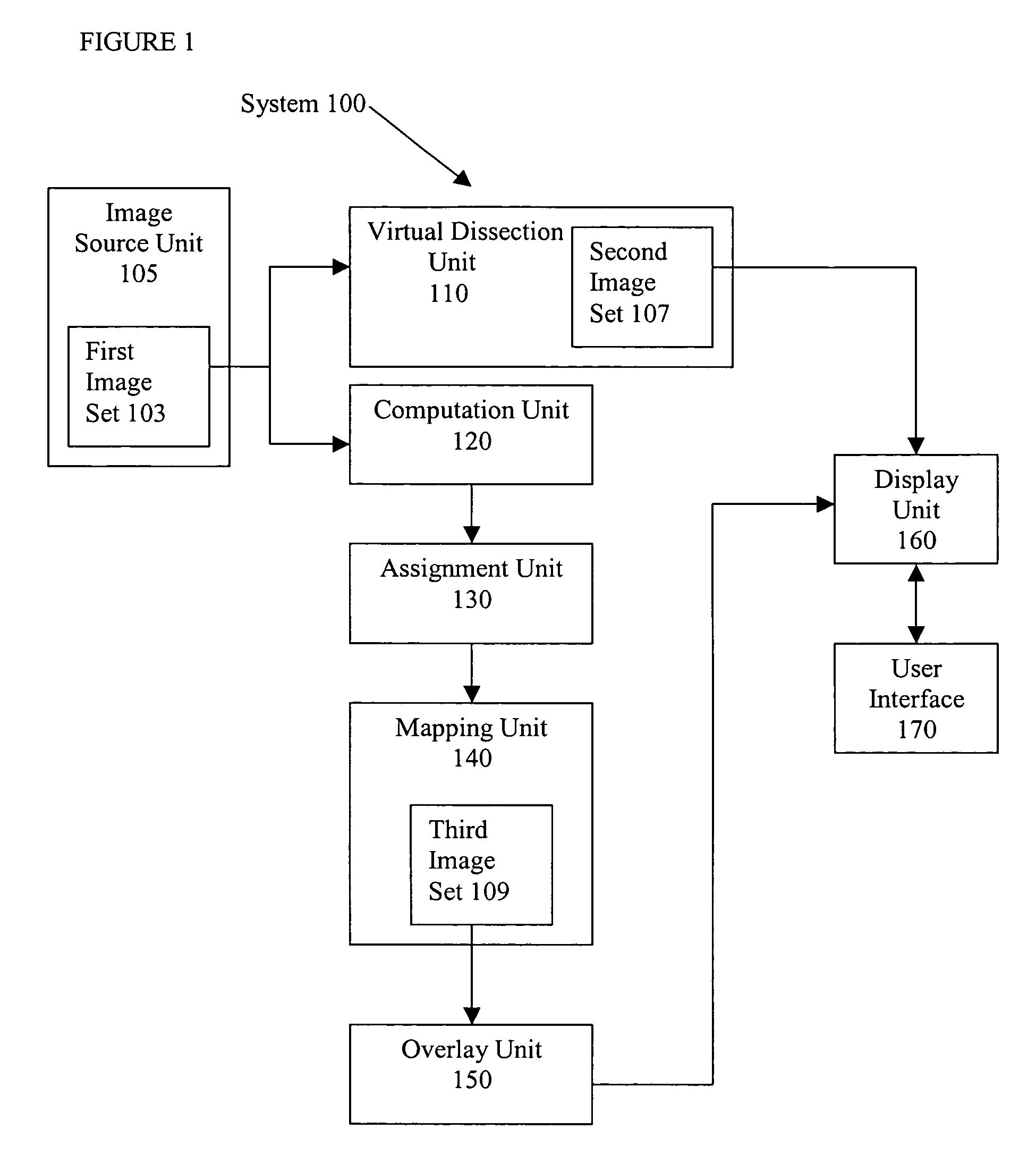
[0026]FIG. 1 illustrates an image processing system 100 according to an embodiment of the present invention. The system 100 includes an image source unit 105 which serves as a source for a first image set 103. The first image set 103 is manipulated at various points in the system 100 to generate a second image set 107 and a third image set 109. The second image set 107 and a third image set 109 are derivatives of the first image set 103. Moreover, the system 100 includes a virtual dissection unit 110 and a computation unit 120 in electrical communication with the image source unit 105. The system 100 also includes an assignment unit 130, a mapping unit 140, an overlay unit 150, a display unit 160, and a user interface, 170 in electrical communication with each other, the computation unit 120 and the virtual dissection unit 110. The components of the system 100 may be separate units, may be integrated in various forms, and may be implemented in hardware and / or in software.

[0027]The s...


PUM


Abstract

A system and method for displaying a set of data with a virtually dissected anatomical structure. In an embodiment, the anatomical structure is a colon and various attributes of the colonic lumen are assigned a color. In an embodiment, a virtual dissection of the colon is created by mapping a three-dimensional data set to a two dimensional data set. A plurality of display index values are computed which correspond to the three-dimensional data set. Various colors are assigned to specific display index values. The three-dimensional display index values are mapped to a two-dimensional set of display index values. As directed by a user, various color cues may be displayed with the virtually dissected lumen to provide color highlights to various aspects of the colon, such as highlighting shape, fluid, or fecal presence.

Description

BACKGROUND OF THE INVENTION[0001]Embodiments of the present invention generally relate to a system and method for image processing, and particularly to a system and method for overlaying a set of coded data on a virtually dissected anatomical structure.[0002]Medical diagnostic imaging systems encompass a variety of imaging modalities, such as x-ray systems, computerized tomography (CT) systems, ultrasound systems, electron beam tomography (EBT) systems, magnetic resonance (MR) systems, and the like. Medical diagnostic imaging systems generate images of an object, such as a patient, for example, through exposure to an energy source, such as x-rays, passing through a patient, for example. The generated images may be used for many purposes. For instance, internal defects in an object may be detected. Additionally, changes in internal structure or alignment may be determined. Fluid flow within an object may also be represented. Furthermore, the image may show the presence or absence of ...

Claims


Application Information

Patent Timeline
Patent Type & Authority Patents(United States)
IPC IPC(8): G06K9/00G09G5/00G09G5/02G06T7/00G06T15/20G06T17/40
CPCG06T7/0012G06T19/00G06T2207/30028G06T2210/41G06T2219/021G06T2219/2012
Inventor SIROHEY, SAAD AHMEDAVINASH, GOPAL B.KNOPLIOCH, JEROME FRANCOISLAUNAY, LAURENTCAPOLUNGHI, RENAUD
Owner GE MEDICAL SYST GLOBAL TECH CO LLC
Why Eureka
Try Eureka