Disengageable pulley device

a pulley and disengage technology, applied in the field of freewheels, can solve the problems of belt being subjected to very considerable stress, abnormal belt fatigue, and associated risks of breakage, and achieve the effect of preventing belt disengagement and reducing the total mass of the disengaged pulley

Inactive Publication Date: 2012-05-08
AB SKF
View PDF246 Cites 32 Cited by
  • Summary
  • Abstract
  • Description
  • Claims
  • Application Information

AI Technical Summary

Benefits of technology

[0009]Embodiments, described herein seek, in particular, to provide a disengageable pulley which is relatively insensitive to torsion, has a small number of parts, entails a reduced manufacturing cost, is simple to mount and has a high load capacity.

Problems solved by technology

If there is a rigid coupling between the pulley and alternator shaft, the belt is subjected to very considerable stresses during these instantaneous speed variations, with detrimental effects such as abnormal belt fatigue and the associated risks of breakage, slipping of the belt on the pulley, or else vibration of the belt strands between the pulleys.
The inner races of the bearing and of the freewheel, along with the shaft on which these parts are mounted, are separate components and hence relatively costly to manufacture separately, to manage and to assemble.
The freewheel is of the roller type and requires that lock-up ramps or faces are machined and that each roller is combined with an individual bearing spring, a situation which proves to be relatively costly.
This results in increased manufacturing costs.

Method used


Image

  • Disengageable pulley device
  • Disengageable pulley device
  • Disengageable pulley device

Examples


Embodiment Construction

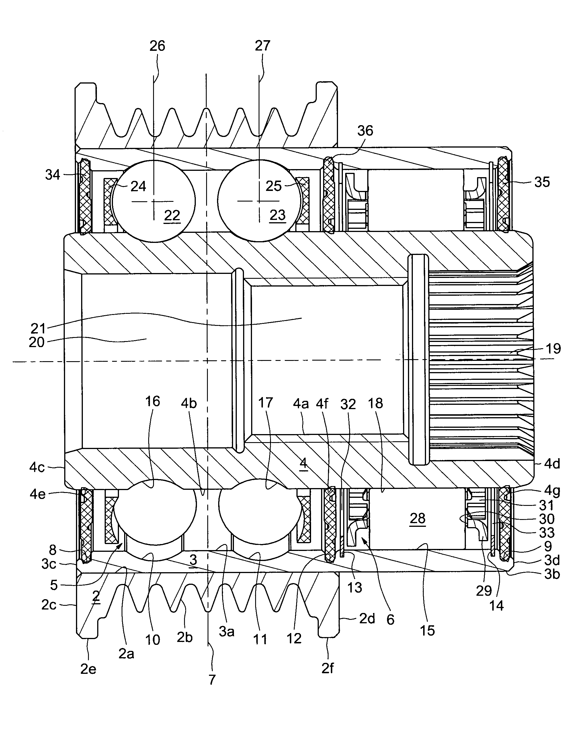
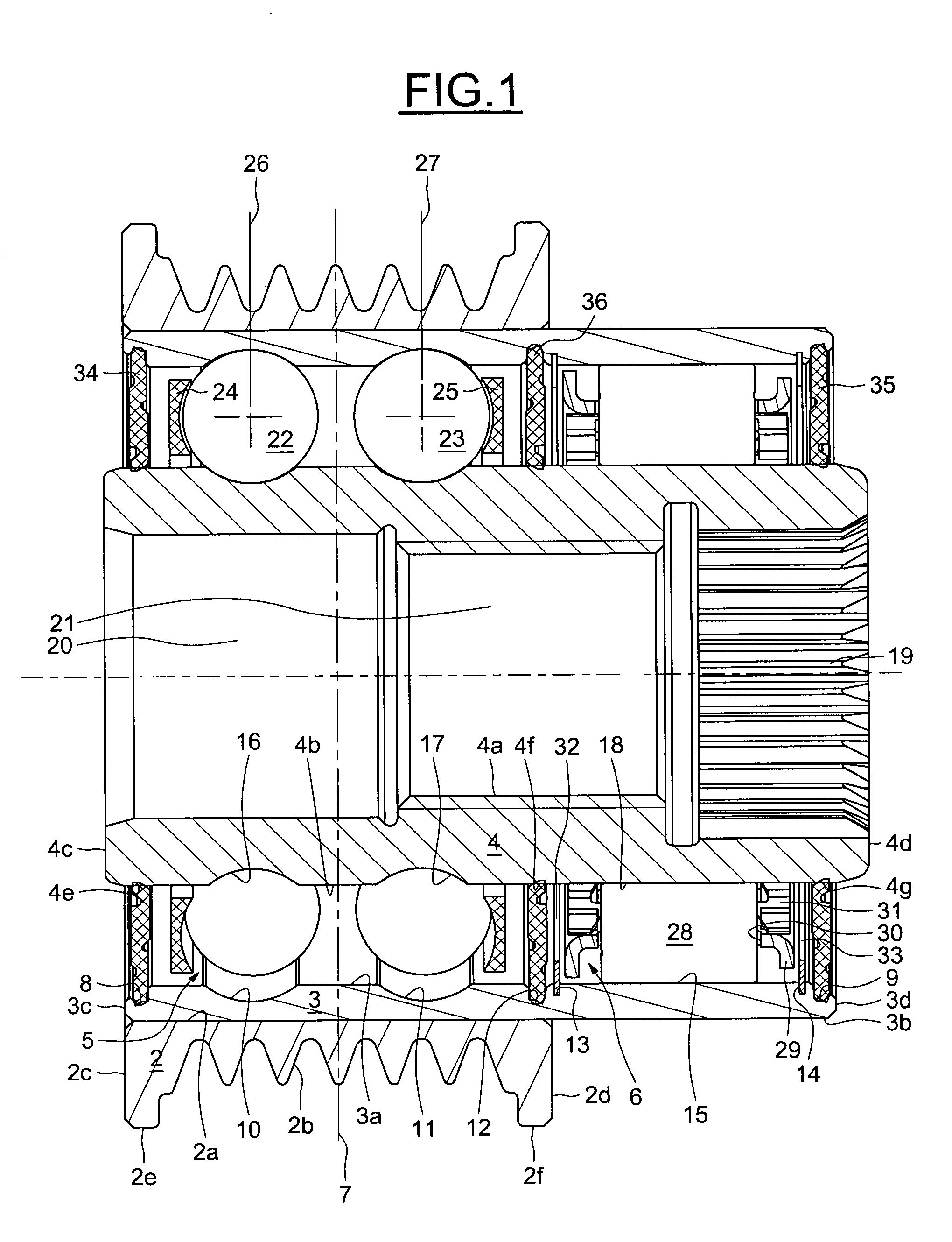
[0033]As can be seen from the figures, the disengageable pulley 1 includes a rim 2, an outer race 3, an inner race 4, a rolling bearing 5 and a freewheel 6. The rolling bearing 5 and the freewheel 6 are arranged between the outer race 3 and inner race 4.

[0034]The rim 2 takes the form of a one-piece component made of synthetic material or metal, for example a light alloy. The rim 2 includes a bore 2a, an active outer surface 2b provided with circular grooves and ribs which are intended to cooperate with a belt (not shown), in particular a poly-V-type belt, and two opposed radial end surfaces 2c and 2d extending from the ends of the bore 2a. At each of its axial ends, the pulley is provided with flanks 2e and 2f whose diameter is slightly larger than the diameter of the active surface 2b, the two flanks ensuring that the belt is correctly guided laterally on the pulley. The rim 2 is symmetrical with respect to a radial plane 7.

[0035]The outer race 3 has a bore 3a, a cylindrical outer ...


PUM


Abstract

Disengageable pulley device comprising a pulley mounted on a shaft by means of a rolling bearing and of a freewheel, the pulley comprising a rim mounted on the periphery of a one-piece outer race of substantially tubular shape comprising, on an inner surface, at least one raceway for rolling elements and at least one contact seat of cylindrical revolution for lock-up elements of the freewheel, a one-piece inner race forming a torque transmission shaft and including, on an outer surface coming opposite the outer race, at least one raceway for the rolling elements and at least one contact seat of cylindrical revolution for the lock-up elements of the freewheel.

Description

BACKGROUND OF THE INVENTION[0001]1. Field of the Invention[0002]The invention relates to the field of freewheels and more particularly to the field of disengageable pulleys equipped with freewheels used, for example, to drive alternators in a motor vehicle.[0003]2. Description of the Relevant Art[0004]Disengageable pulleys are being increasingly used to overcome the detrimental effects of acyclic running or sudden engine accelerations or decelerations which occur in combustion engines, in particular at low engine speeds and especially in diesel engines.[0005]In these conditions, the drive belt, which is connected to the engine by the crankshaft pulley, decelerates sharply while the driven pulley, the alternator pulley for example, has a tendency, as a result of inertia, to continue to turn at the same speed. If there is a rigid coupling between the pulley and alternator shaft, the belt is subjected to very considerable stresses during these instantaneous speed variations, with detri...

Claims


Application Information

Patent Timeline
Patent Type & Authority Patents(United States)
IPC IPC(8): F16D41/07F16H55/36
CPCF16C33/58F16D41/069F16H55/36F16C19/08F16C33/581F16C2361/63F16D41/07
Inventor BARRAUD, PIERRE-JULIENHINGOUET, GWENAELGABOREL, JEAN-PHILIPPE
Owner AB SKF
Why Eureka
Try Eureka