Semiconductor integrated circuit device
a technology of integrated circuit devices and semiconductors, applied in static storage, digital storage, instruments, etc., to achieve the effect of improving the reliability reducing the number of times of disturbance, and reducing the size of semiconductor integrated circuit devices
- Summary
- Abstract
- Description
- Claims
- Application Information
AI Technical Summary
Benefits of technology
Problems solved by technology
Method used
Image
Examples
first embodiment
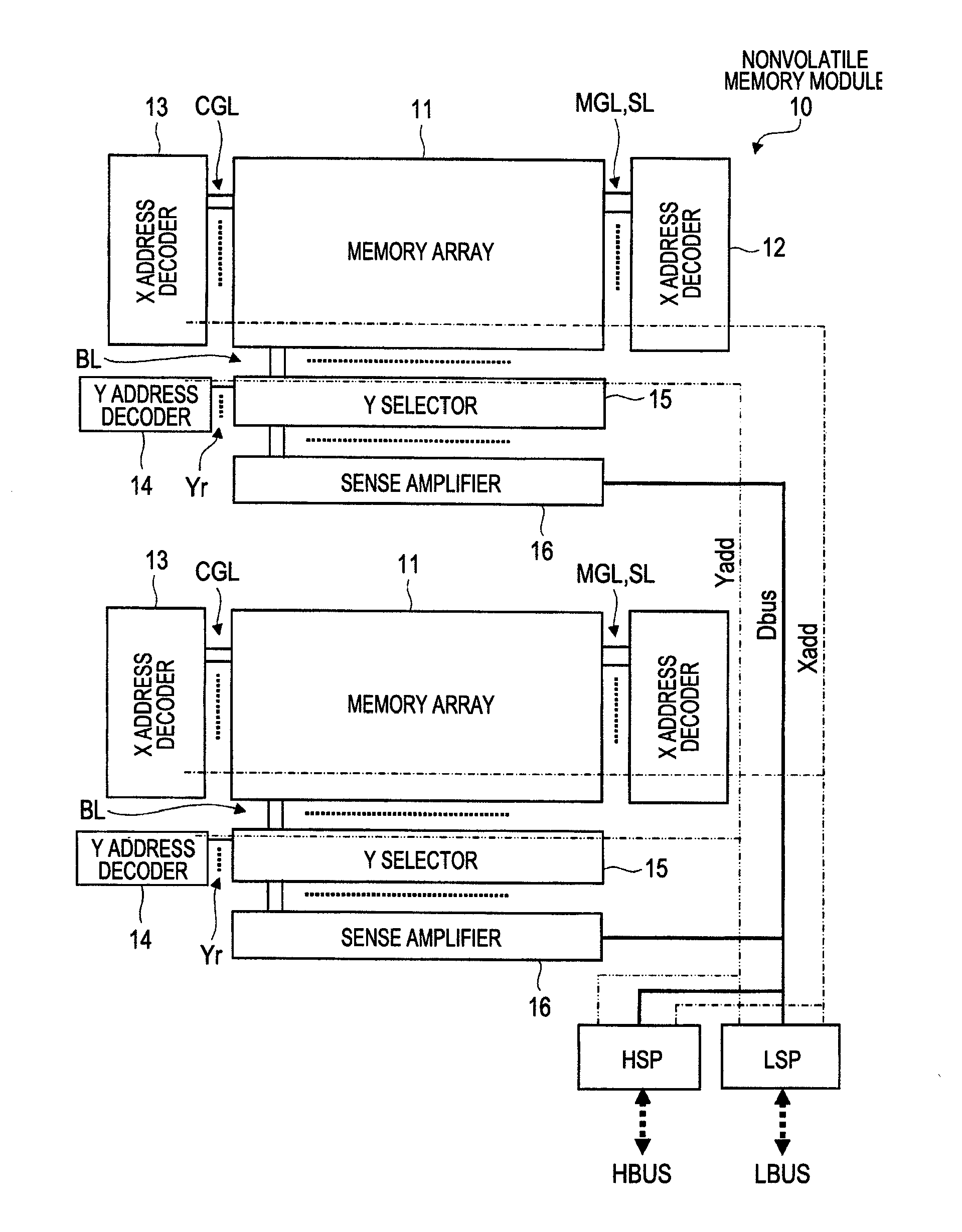
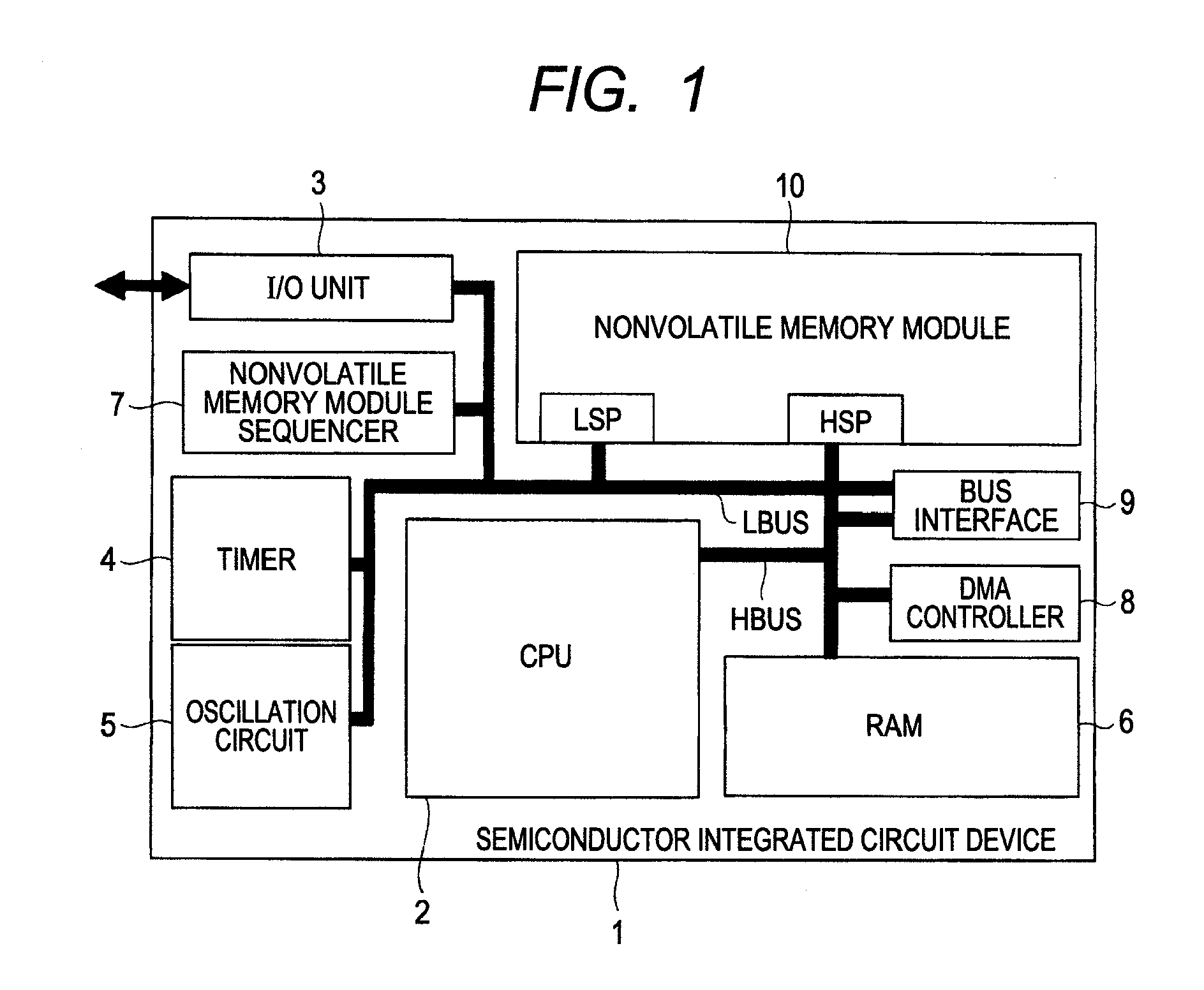
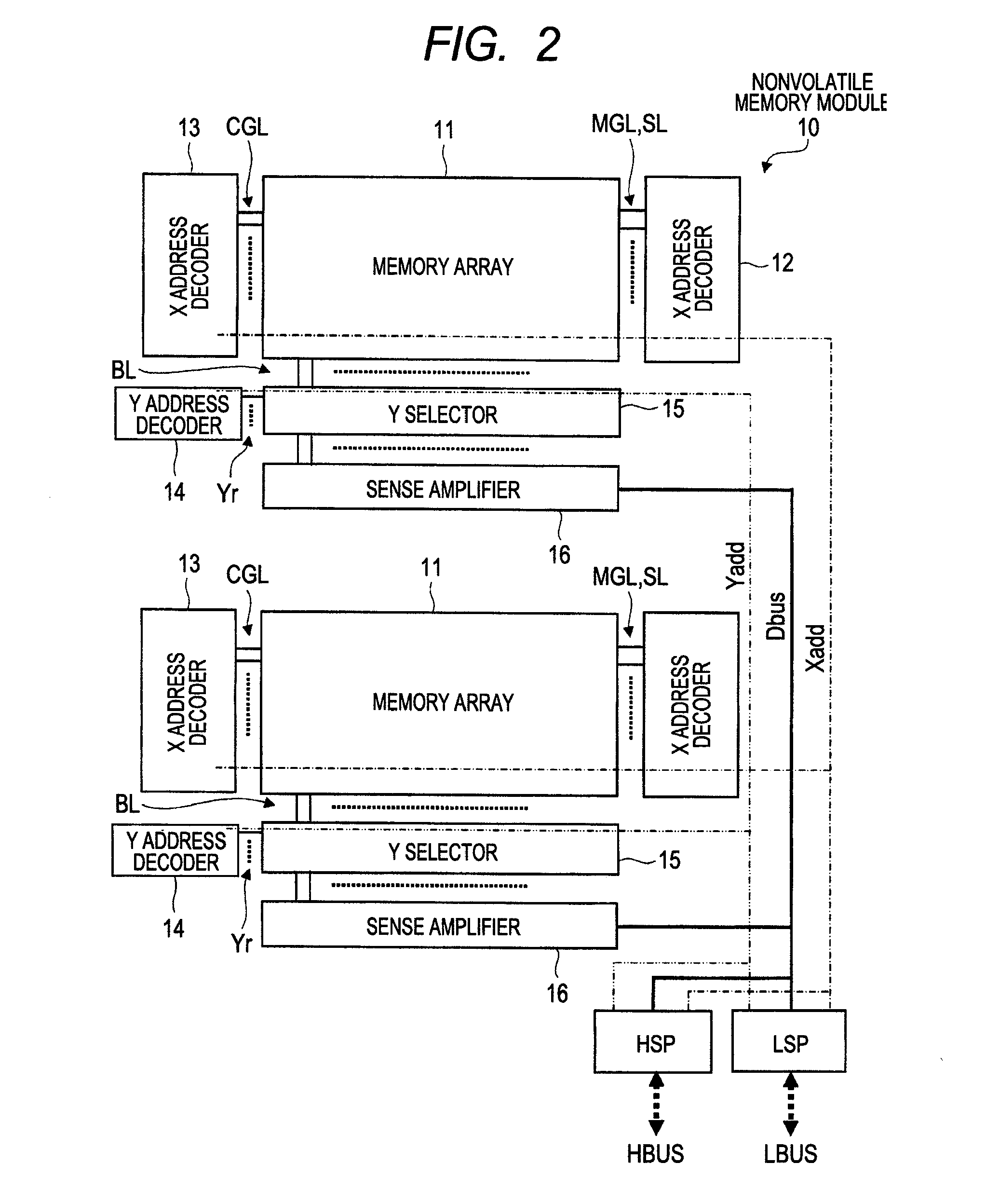
[0051]FIG. 1 is a block diagram showing a configuration example of a semiconductor integrated circuit device according to a first embodiment of the present invention. FIG. 2 is an illustrative diagram showing a configuration example of a nonvolatile memory module provided in the semiconductor integrated circuit device of FIG. 1. FIG. 3 is an illustrative diagram showing a configuration example of a memory cell provided in the nonvolatile memory module of FIG. 2. FIG. 4 is an explanatory table listing voltage conditions for write, erase, and read in the memory cell of FIG. 3. FIG. 5 is an illustrative diagram showing a configuration example of a memory array shown in FIG. 2. FIG. 6 is a timing chart showing operating waveforms of signals representing an example of write operation in a memory array of FIG. 18. FIG. 7 is a timing chart representing an example of write operation in the memory array of FIG. 5. FIG. 8 is a timing chart showing operating waveforms of signals in erase opera...
second embodiment
[0111]FIG. 13 is an illustrative diagram showing a configuration example of a memory array according to a second embodiment of the present invention. FIG. 14 is an illustrative diagram showing another configuration example of the memory array of FIG. 13.
[0112]In the second embodiment, FIG. 13 shows an example of modification to the first embodiment, wherein the elements of the MG buffer circuits 21 shown in FIG. 5 are replaced by switch transistors.
[0113]The MG buffer circuits 21 shown in FIG. 5 for the preceding first embodiment are, for example, of a CMOS type which comprises a p-conducting (P-type) MOSFET and an n-conducting (N-type) MOSFET which are not shown. However, in FIG. 13 for the second embodiment, the components of the MG buffer circuits 21 are replaced by switch transistors SWs and these transistors SWs (e.g., N-type MOSFETs) are on / off controlled by a control signal MGT. Therefore, a control signal MGDN is only supplied to the MG buffer circuits 21.
[0114]FIG. 14 shows...
third embodiment
[0119]FIG. 15 is a set of graphs to explain an example of threshold voltage control for memory cells according to a general method of storing one unit of data per cell. FIG. 16 is a set of graphs to explain an example of threshold voltage control for memory cells provided in a memory array according to a third embodiment of the present invention. FIG. 17 is an illustrative diagram showing a configuration example of a memory array according to the third embodiment of the present invention.
[0120]In the third embodiment, a complementary storage method that stores one unit of data using two memory cells is applied to the memory array configuration described in the preceding first embodiment.
[0121]Here, the complementary storage method is explained.
[0122]In the general method of storing one unit of data using one memory cell (storing one unit of data per cell), the threshold voltage for the transistors constituting each memory cell is controlled so that the threshold voltage in a data wr...
PUM
 Abstract
Description
Claims
Application Information
 - R&D
- Intellectual Property
- Life Sciences
- Materials
- Tech Scout
- Unparalleled Data Quality
- Higher Quality Content
- 60% Fewer Hallucinations
Browse by: Latest US Patents, China's latest patents, Technical Efficacy Thesaurus, Application Domain, Technology Topic, Popular Technical Reports.
© 2025 PatSnap. All rights reserved.Legal|Privacy policy|Modern Slavery Act Transparency Statement|Sitemap|About US| Contact US: help@patsnap.com


