Power factor correction converter

a converter and power factor technology, applied in the direction of electric variable regulation, process and machine control, instruments, etc., can solve the problems of harmonic current and error, and achieve the effect of preventing the deterioration of transient responsiveness and the effect of reducing the voltage of output voltag

Active Publication Date: 2012-05-15
MURATA MFG CO LTD
View PDF12 Cites 11 Cited by
  • Summary
  • Abstract
  • Description
  • Claims
  • Application Information

AI Technical Summary

Benefits of technology

[0015]To overcome the problems described above, preferred embodiments of the present invention provide a PFC converter that provides both the responsiveness of P control and the stability of PI control and that prevents a variation in output voltage due to a variation in input voltage or load while preventing deterioration of transient responsiveness.
[0018]According to various preferred embodiments of the present invention, a variation in output voltage due to a variation in input value or load is effectively prevented while deterioration of transient responsiveness is also effectively prevented.

Problems solved by technology

This results in harmonic current.
That is, even in a stable state, an error is present.

Method used


Image

  • Power factor correction converter
  • Power factor correction converter
  • Power factor correction converter

Examples


first preferred embodiment

[0026]A PFC converter according to a first preferred embodiment of the present invention will be described with reference to FIG. 2 to 6.

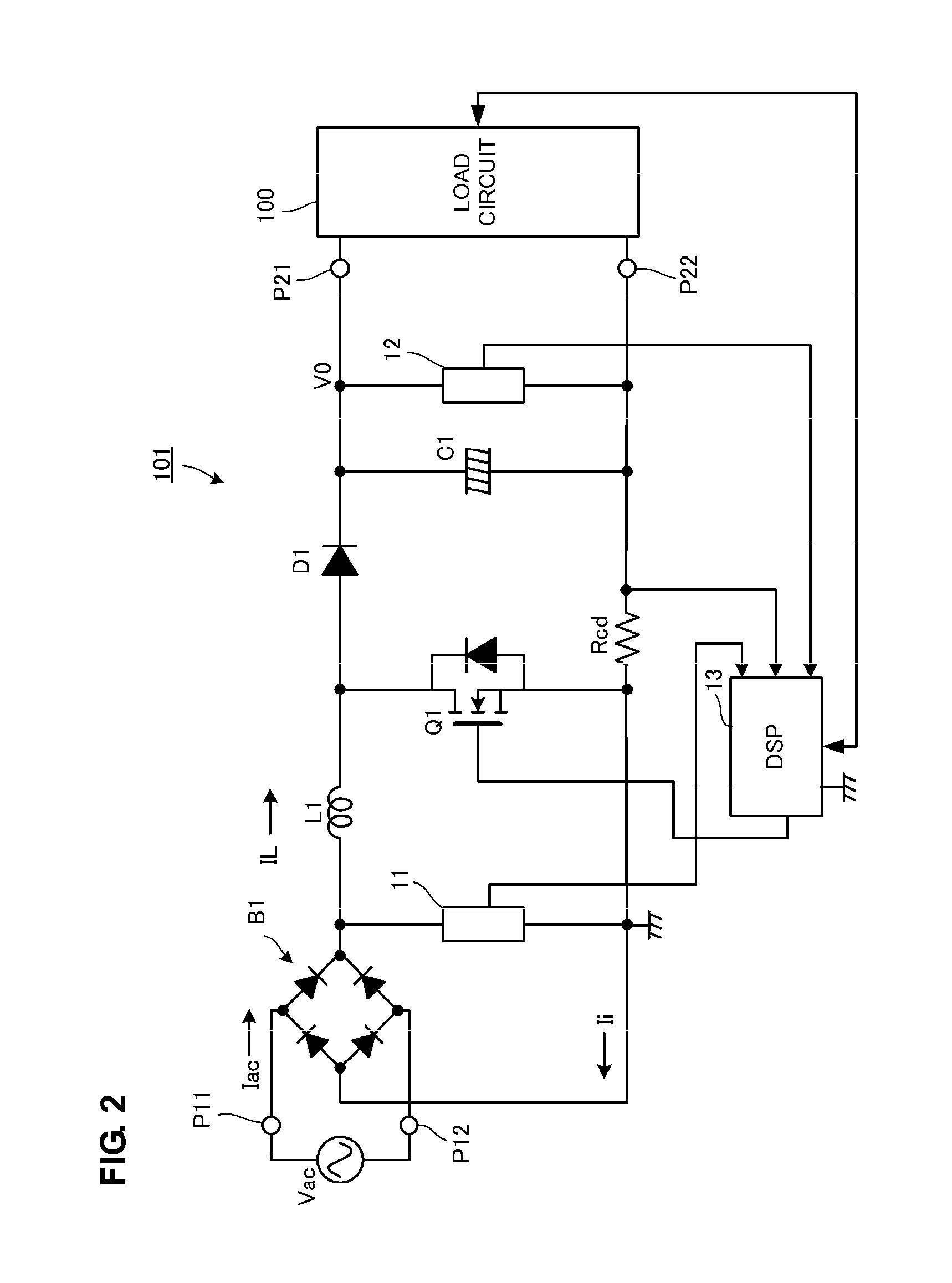
[0027]FIG. 2 is a circuit diagram of the PFC converter according to the first preferred embodiment. In FIG. 2, numerals P11 and P12 are the input ports of a PFC converter 101, and numerals P21 and P22 are the output ports of the PFC converter 101. An alternating-current input power supply vac, which is a commercial alternating-current power supply, is input into the input port P11 and P12, and a load circuit 100 is connected to the output ports P21 and P22.

[0028]The load circuit 100 is preferably, for example, a circuit including a DC-DC converter and an electronic device that receives power supply therefrom.

[0029]A diode bridge B1, which full-wave rectifies the alternating-current voltage of the alternating-current input power supply vac, is disposed in the input stage of the PFC converter 101. The diode bridge B1 corresponds to a “rectifier circu...

second preferred embodiment

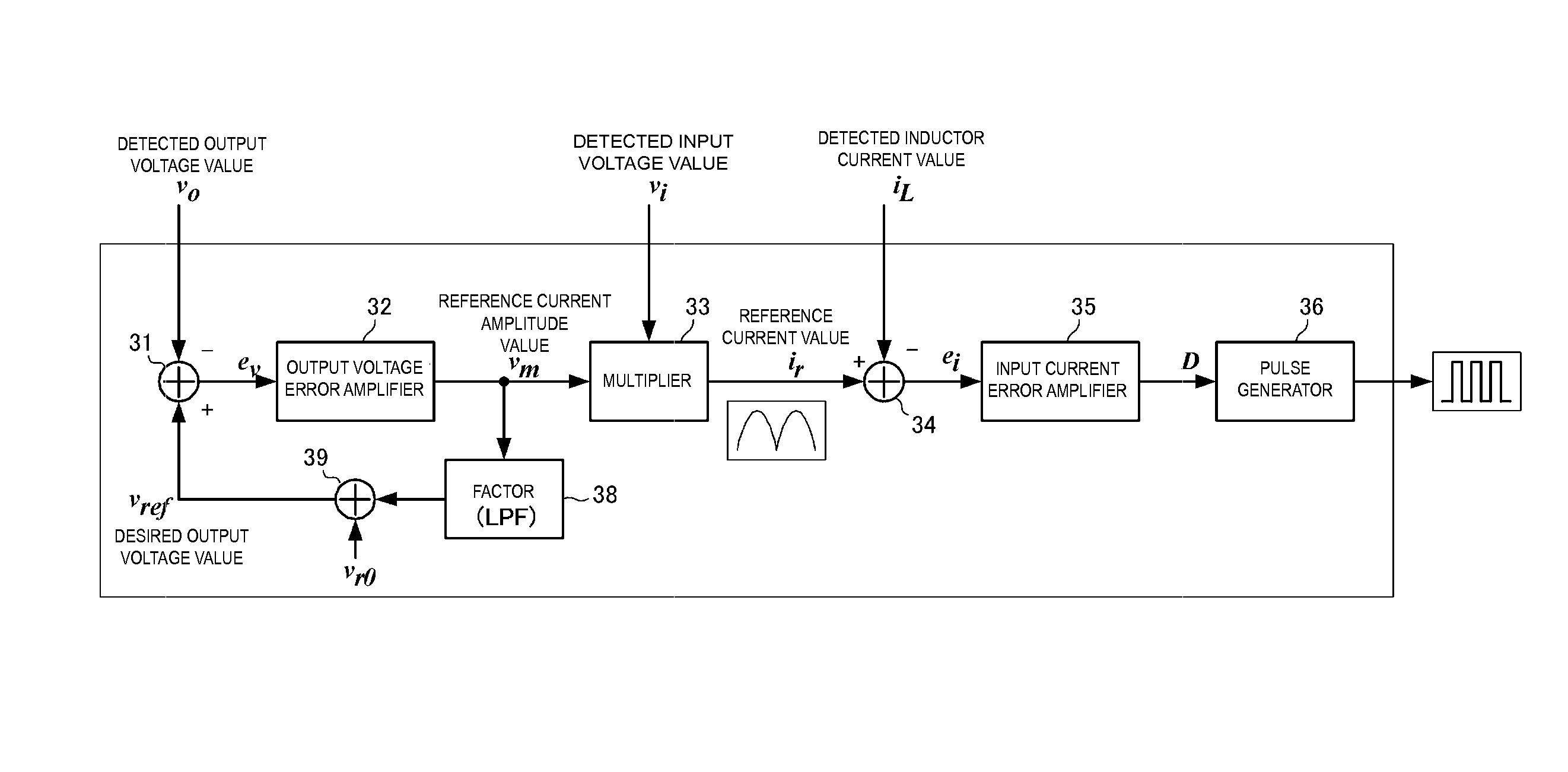
[0045]In the first preferred embodiment, as shown in FIGS. 2 and 4, switching control is preferably performed using the digital signal processing circuit 13 defined by DSP. On the other hand, a second preferred embodiment of the present invention is an example in which the output voltage error amplifier 32 shown in FIG. 4 is preferably defined by an analog element.

[0046]FIG. 6 is a circuit diagram of an output voltage error amplifier according to the second preferred embodiment. An input voltage Vref of a non-inverting input terminal (+) of an operational amplifier OP is represented by Formula (1) below. In Formula (1), Vm is the output voltage of the operational amplifier OP (the output of the output voltage error amplifier), vo is a detected output voltage value, and Vref is a desired output voltage value.

Vref=(vr0 / Rr1+vm / Rr3) / (1 / Rr1+1 / Rr2+1 / Rr3)  (1)

[0047]Note that since a capacitor Cref is connected in parallel with a resistor Rr2, the temporal variation in the desired output vo...


PUM


Abstract

A power factor correction converter includes an output voltage error amplifier which functions as a proportioning device in a low-frequency range in order to stabilize the output voltage by feedback control and obtains a reference current amplitude value vm by multiplying an error ev between a desired output voltage value Vref and a detected output voltage value vo by a predetermined proportionality factor. A factor element multiplies the reference current amplitude value by a predetermined factor and adds the resulting value to a reference value to obtain a desired output voltage value. The factor element functions as a low-pass filter by changing the desired output voltage value Vref in accordance with the reference current amplitude value vm in a low-frequency range and reducing the factor value in a high-frequency range.

Description

BACKGROUND OF THE INVENTION[0001]1. Field of the Invention[0002]The present invention relates to an AC-DC converter that receives an alternating-current power supply and outputs a direct-current voltage and, in particular, to a PFC (power factor correction) converter that suppresses harmonic current.[0003]2. Description of the Related Art[0004]Electric apparatuses connected to a commercial power supply are subjected to harmonic current restriction corresponding to their power capacity. Switching power supply devices that receive a commercial power supply typically include a PFC converter in order to satisfy such a restriction.[0005]A general switching power supply device using a commercial alternating-current power supply as an input power supply rectifies and smoothes the commercial alternating-current power supply to convert it into a direct-current voltage and then switches the direct-current voltage in a DC-DC converter. Thus, the input current is discontinuous and significantly...

Claims


Application Information

Patent Timeline
Patent Type & Authority Patents(United States)
IPC IPC(8): H02M1/12G05F1/40
CPCH02M1/4225H02M3/156Y02B70/126H02M2001/0022Y02B70/10Y02P80/10H02M1/0022
Inventor UNO, YOSHIYUKI
Owner MURATA MFG CO LTD
Why Eureka
Try Eureka