
High mass resolution low aberration analyzer magnet for ribbon beams and the system for ribbon beam ion implanter

a technology of analyzer magnet and ribbon beam, which is applied in the field of mass analyzing ribbon shaped ion beams, can solve the problems of process failure, process failure, process failure, etc., and achieve the effects of increasing the mass resolving power of the magnet, reducing the focal spot size, and increasing the dispersion

Inactive Publication Date: 2012-05-22
HUANG YONGZHANG +1
View PDF4 Cites 6 Cited by
  • Summary
  • Abstract
  • Description
  • Claims
  • Application Information

AI Technical Summary

Benefits of technology

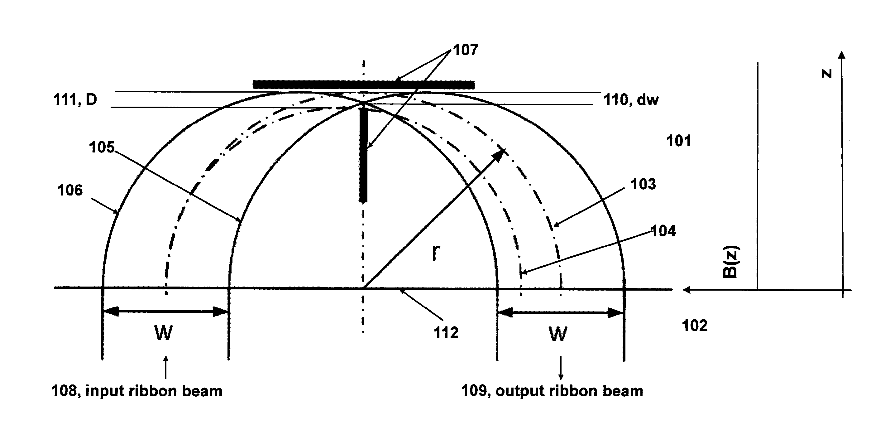
"The present invention provides a system for implanting workpieces using a ribbon shaped ion beam. The invention solves problems associated with previous methods, such as poor process control and dose uniformity. The invention uses a single dipole magnet that mass analyzes the ribbon beam and provides uniform dose of ions to the target wafer. The magnet has a bending angle of 180 degrees, which allows for single-scan implantation of large wafers. The system also includes a field clamp to reduce fringe field effects and a resolving aperture to selectively pass only desired ions. The invention increases mass resolving power by shaping the magnet pole surface to provide non-constant field distribution and curving the entrance and exit edges of the magnet poles to minimize distortions and aber."

Problems solved by technology

Variation across the wafer can cause process failures.
Angle variation across the wafer can cause process failures.
Energy contamination can cause process failures as well.
This particle contamination can cause low yield.
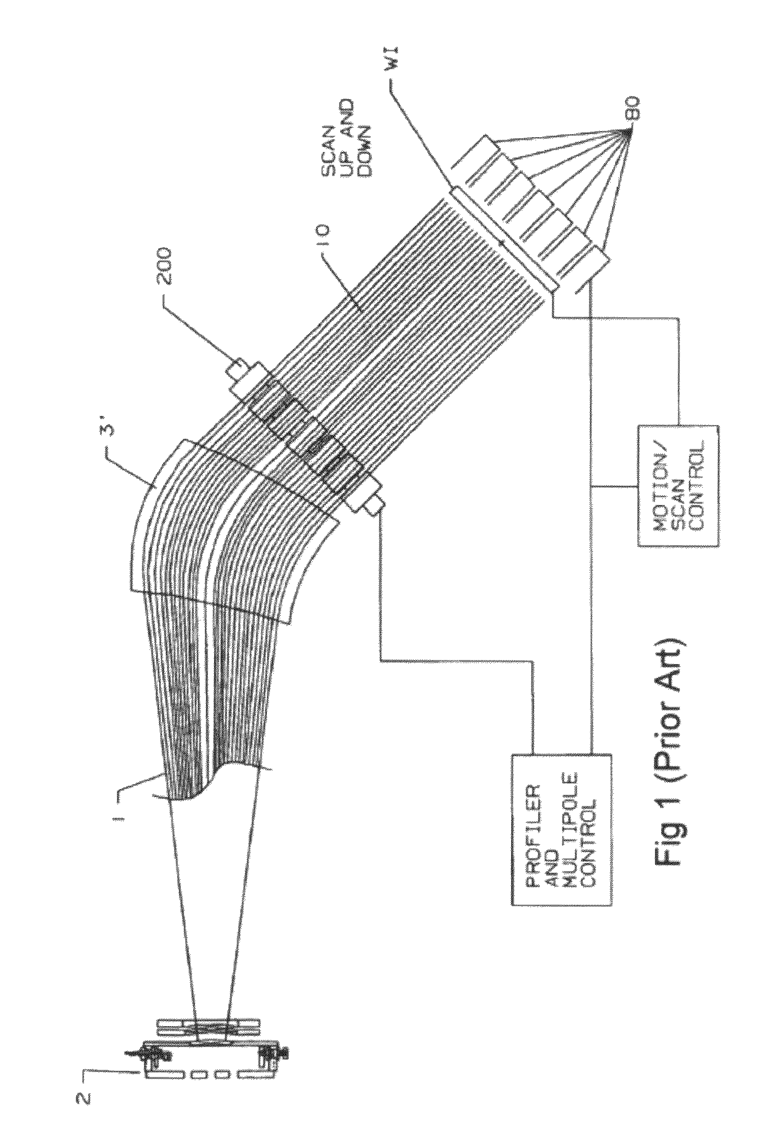
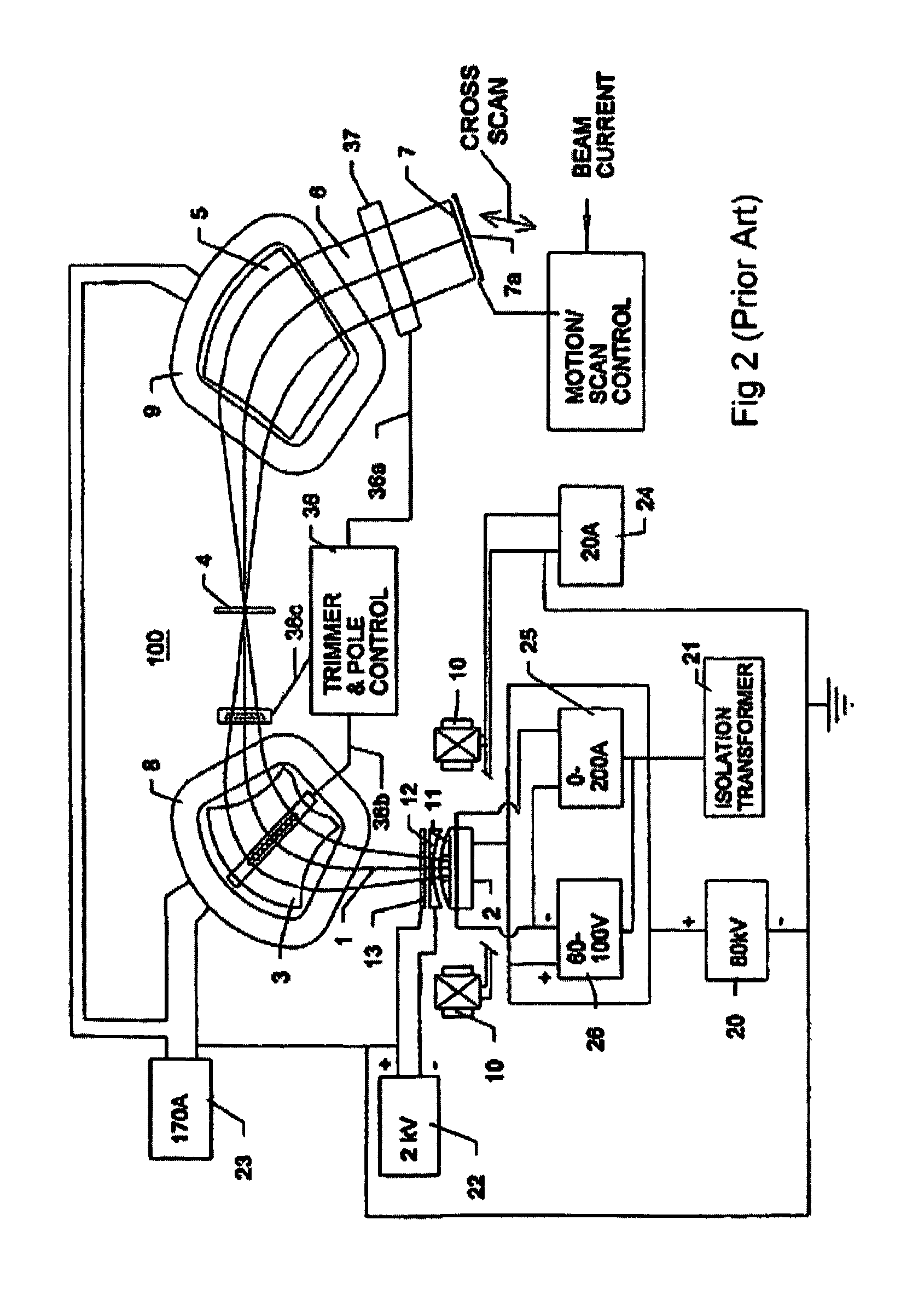
Unfortunately however, this two-magnet system has severe drawbacks: it is complex and expensive; and is only manufactured to produce ribbon ion beams up to 300 mm in size (See Prior Art FIG. 2, reproduced from U.S. Pat. No. 5,350,926).
Due to the complex interactions between the ion beam and the magnetic field applied for beam expansion, this approach creates severe technical, practical, and process-related problems that increase the total production cost of such equipment and lead to more complicated operation procedures for carrying out the ion implantation.
In particular, the beam path through this system is relatively long, and at low energies and high beam currents it becomes increasingly difficult to control the uniformity of the ion beam and the angular variation within the beam to meet the precision required by certain commercial processes.
If the aberration is large, this will cause large variation in the implantation.
However, the ribbon beam that these two magnets produce still has large aberrations.
In the end, this brings aberration to the ribbon beam.
This aberration can be amplified by the decel system which is one of the reasons that the implanter system of FIG. 2 has difficulty in producing productive low energy ion beams.
However, because of the unsatisfactory performance of the mass analyzer magnet, these types of ion implantation systems often are not a viable solution for performing serial mode implantation with a high-current, high-uniformity ion beam that has controllable shapes and sizes.

Method used


Image

  • High mass resolution low aberration analyzer magnet for ribbon beams and the system for ribbon beam ion implanter
  • High mass resolution low aberration analyzer magnet for ribbon beams and the system for ribbon beam ion implanter
  • High mass resolution low aberration analyzer magnet for ribbon beams and the system for ribbon beam ion implanter

Examples


Embodiment Construction

[0081]The present invention will now be described with reference to the drawings wherein like reference numerals are used to refer to like elements throughout. The invention provides methods and systems for the provision of a mass analyzed ribbon-beam for ion implantation of workpieces such as semiconductor wafers. One implementation of the invention is illustrated and described hereinafter with respect to the drawing figures. The illustrations and following descriptions are exemplary in nature, and not limiting. Thus, it will be appreciated that variants of the illustrated systems and methods and other such implementations apart from those illustrated herein are deemed as falling within the scope of the present invention and the appended claims.

I. The Technical Underpinnings of the Present Invention

A. The Conventional Mass Analyzing Magnet

[0082]For conventional mass analyzer magnet, it is the sector magnets that perform mass analysis. FIG. 7a shows a sector magnet and the ion beam ...


PUM


Abstract

The present invention provides a mass analyzing magnet which can bend a very wide charged particle ribbon beams through angles between 90 to 200 degrees. The shorter dimension of the ribbon beam is aligned with the magnetic field. The magnet can focus the longer dimension of the ribbon beam through a resolving slot inside the magnet for mass or momentum analysis. The magnet pole is shaped to increase the mass resolving power and to provide the focusing force in the direction of the shorter dimension of the ribbon beam. This magnet can achieve high mass resolving power with very small system aberrations for very wide ribbon beam. This feature is of significant value, for example, in the ion implantation industry. The ribbon beam width can be 300 mm, 450 mm and even 1000 mm. Integrated with the present invention, the ion implanter systems can be built to provide mass analyzed ribbon beams for various applications. The system will have much lower cost and much better ribbon beam quality than the ion implanters which are using conventional mass analyzing magnet.

Description

CROSS-REFERENCE TO RELATED APPLICATIONS[0001]This application claims priority to the U.S. Provisional Patent Application No. 61 / 210,870 filed on Mar. 24, 2009 and the U.S. Provisional Patent Application No. 61 / 268,087 filed on Jun. 8, 2009. This application also claims priority under the Paris convention of Chinese Patent Application No. 200910060092.1 filed on Jul. 23, 2009.FIELD OF THE INVENTION[0002]The present invention is concerned generally with mass analyzing ribbon shaped ion beams; it is directly specific to magnets which are able to bend a high aspect ratio ribbon ion beam, and focus the ion beam for mass analysis with high resolution, high acceptance and small aberration. The present invention is also concerned generally with the integration of ion beam systems with invented magnets to provide mass analyzed ribbon shaped ion beams for various applications.BACKGROUND OF THE INVENTION[0003]The doping of semiconductors with electrically active elements is now performed almos...

Claims


Application Information

Patent Timeline
Patent Type & Authority Patents(United States)
IPC IPC(8): H01J3/20H01J49/20H01J37/14
CPCH01J37/05H01J37/153H01J37/3171H01J2237/057H01J2237/08
Inventor HUANG, YONGZHANGHU, XINPING
Owner HUANG YONGZHANG
Learn More