Method of operating a high pressure ethylene polymerisation unit

a polymerisation unit and high-pressure technology, applied in the direction of supercritical condition processes, chemical/physical/physical-chemical processes, chemistry apparatuses and processes, etc., can solve the problems of minor leakage of reaction medium into the cooling jacket, thermal runaway, and care in order to control reaction temperatur

Inactive Publication Date: 2012-05-29
TOTAL RES & TECH FELUY
View PDF6 Cites 8 Cited by
  • Summary
  • Abstract
  • Description
  • Claims
  • Application Information

AI Technical Summary

Problems solved by technology

However, in tubular reactors, care must be taken in order to control the reaction temperature or else thermal runaway may occur due to the exothermic nature of the reaction.
When these occur, the fissures steadily grow, creating a minor leakage of reaction medium into the cooling jacket.
As the fissures expand, more and more polymer and monomer build up in the cooling jacket, causing a blockage in the circulation of the cooling water.
Eventually the polymerisation temperature can no longer be efficiently controlled, which increases the risk of thermal runaway of the reaction.
This is a heavy financial burden, not only in terms of equipment cost, but also in terms of lost production time.
This problem can occur in any double tube within a high pressure ethylene polymerisation unit, whether in the tubular reactor or, for example, in the recycle systems of unreacted monomer.
The higher the pressure within the tube, the higher the risk of a leak occurring.
However, these detectors cannot be installed online.
Instead, the cooling water must be continuously sampled and analysed, which is not only an unnecessary waste, but also a complex process.
In particular, during start-up of the polymerisation process, the cooling water in the first reactor zone is heated with hot water or steam, but the catalytic gas detector cannot withstand these conditions and is often damaged.
However, sampling cooling water from each cooling circuit and transferring it to each of the circuit's own independent condenser and gas detector is neither efficient, nor cost effective.
Unfortunately, it is then impossible to identify which reactor tube has incurred the leak, if ethylene is detected.
Even by carefully regulating the pressure valves, it is almost impossible to have a continuous simultaneous passage of gas from all the reactor zones to the detector.

Method used


Image

  • Method of operating a high pressure ethylene polymerisation unit
  • Method of operating a high pressure ethylene polymerisation unit
  • Method of operating a high pressure ethylene polymerisation unit

Examples


Embodiment Construction

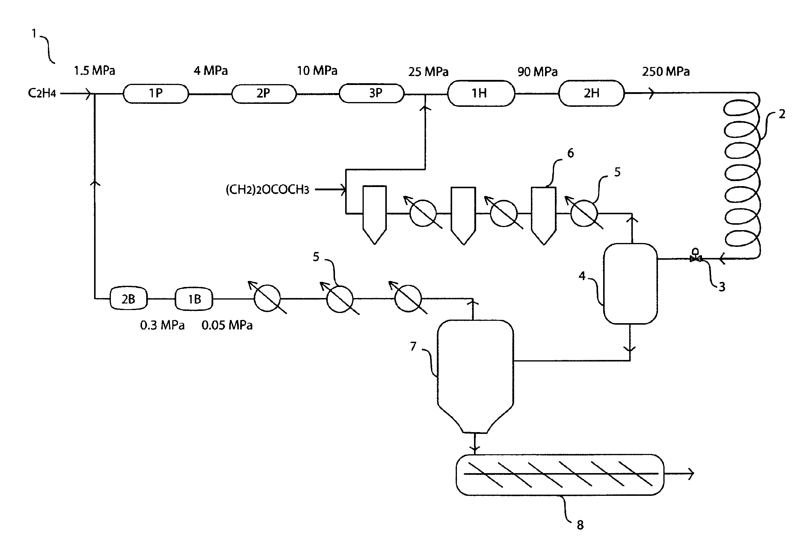
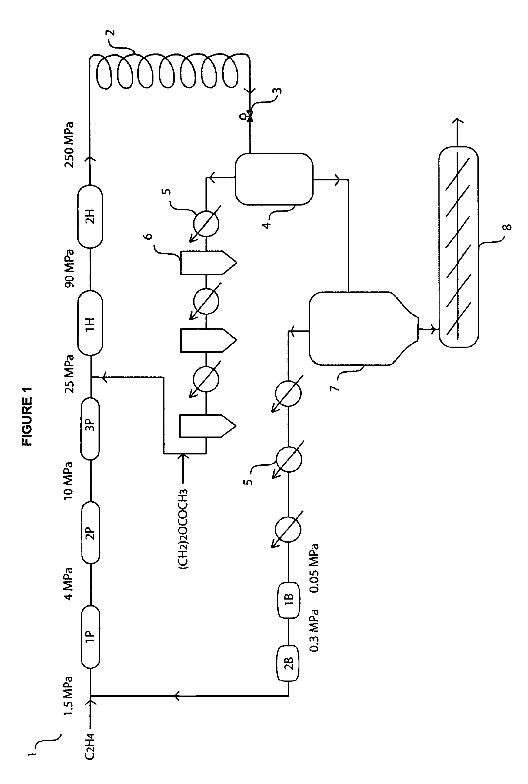
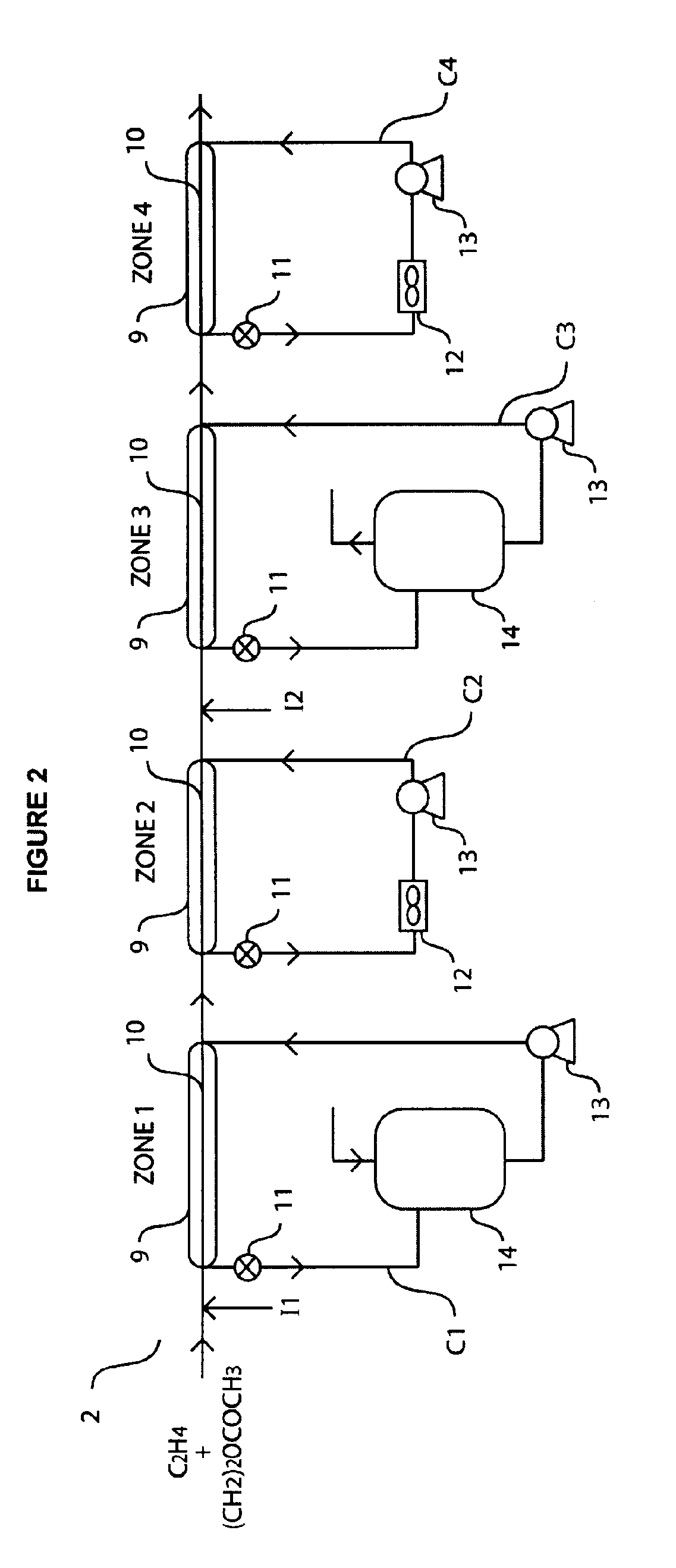
[0019]The person skilled in the art will appreciate that the invention can be applied to detecting leaks in any high pressure ethylene polymerisation unit comprising a tubular reactor made up of a plurality of interconnected double tubes. The polymerisation process is usually carried out under a pressure of at least 50, particularly of at least 100, 150, 200 or 250 MPa. The unit may further comprise a medium pressure recycle for recycling unreacted reactants also comprising a plurality of interconnected double tubes, wherein the contents to be recycled are under a pressure of at least 20 MPa, particularly of at least 25, 50, 100, 150, 200 or 250 MPa. In general, the higher the pressure in any section of the unit, the more useful the method of the invention will be, since the risk of a leakage increases with increasing pressure.

[0020]The double tubes, which are monitored for leakages, have a central tube and an outer enveloping tube. The medium to be treated, .e.g. to be polymerised ...


PUM

PropertyMeasurementUnit
pressureaaaaaaaaaa
pressureaaaaaaaaaa
temperaturesaaaaaaaaaa

Abstract

The invention relates to a method of operating a high pressure ethylene polymerization unit comprising a tubular reactor, the method characterized in that the electrical conductivity of the aqueous cooling medium is monitored in at least one location. Furthermore, the invention also covers a high pressure ethylene polymerization unit comprising a tubular reactor, the unit characterized in that one or more cooling circuits comprise an electrical conductivity meter. The use of such a polymerization unit is also disclosed.

Description

CROSS-REFERENCE TO RELATED APPLICATIONS[0001]This application claims the benefit of PCT / EP2008 / 056846, filed Jun. 3, 2008, which claims priority from EP 07290711.6, filed Jun. 6, 2007.FIELD OF THE INVENTION[0002]The invention relates to a method of operating a high pressure ethylene polymerisation unit.BACKGROUND OF THE INVENTION[0003]Low density polyethylene (LDPE) having a high degree of long and short chain branching is generally produced in high pressure ethylene polymerisation units. Due to the long chain branching, LDPE exhibits low crystallinity and, when molten, a lower tensile strength and higher ductility than other known polyethylenes. These unique and desirable flow properties allow LDPE to be used for plastic film applications such as plastic bags and film wrap.[0004]Copolymerisation of ethylene with vinyl acetate monomer (VAM) provides a copolymer known as ethylene-vinyl acetate (EVA). This polymer approaches the softness and flexibility of elastomeric materials, yet c...

Claims


Application Information

Patent Timeline
Patent Type & Authority Patents(United States)
IPC IPC(8): B01J19/00C08F2/00C08F210/00C08F110/02
CPCB01J3/008B01J19/20B01J19/242B01J19/243C08F210/02C08F2/00C08F2/01B01J2219/0004B01J2219/00081B01J2219/00085B01J2219/00092B01J2219/00094C08F218/08Y02P20/582
Inventor BARBERO, BERTRAND
Owner TOTAL RES & TECH FELUY
Why Eureka
Try Eureka