Light emitting device having plural light emitting diodes and at least one phosphor for emitting different wavelengths of light

a light emitting diode and light emitting phosphor technology, applied in the direction of luminescent compositions, energy-efficient lighting, sustainable buildings, etc., can solve the problems of reducing color rendering, increasing manufacturing costs, and distorted chemical characteristics of phosphors, so as to improve energy conversion efficiency and improve reliability against vapor

Active Publication Date: 2012-05-29
SEOUL SEMICONDUCTOR
View PDF252 Cites 18 Cited by
  • Summary
  • Abstract
  • Description
  • Claims
  • Application Information

AI Technical Summary

Benefits of technology

[0011]The present invention is conceived to solve the aforementioned problem. An object of the present invention is to provide a white light emitting device in which energy conversion efficiency can be improved by effectively using ultraviolet light as an excitation source of phosphors.
[0012]Another object of the present invention is to provide a white light emitting device in which a light emitting diode for emitting light different in wavelength from light excitatively emitted from a phosphor can be used to improve reliability against vapor and carbon dioxide to which the light emitting device may be easily exposed.
[0021]According to the present invention, a white light emitting device can be provided in which energy conversion efficiency can be improved by effectively using an ultraviolet light emitting diode as an excitation source of a phosphor.
[0022]Further, a light emitting diode for emitting light different in wavelength from light excitatively emitted from a phosphor can be used to improve reliability against vapor and carbon dioxide to which the light emitting device may be easily exposed.

Problems solved by technology

Although such a method of implementing white light provides a simple configuration and an excellent mass-producibility, there is a problem in that the shortages of green and red spectra may reduce color rendering.
However, various phosphors, such as blue, green and red phosphors, are used, thereby increasing manufacturing costs.
In this case, there is a problem in that the light emitting device easily reacts with water vapor and carbon dioxide in the atmosphere during its operation and therefore the chemical characteristics of the phosphor is distorted.
Since the byproduct of such a reaction, H2S gas, corrodes metal such as electrodes within the light emitting device, there is a problem in that the reliability of the light emitting diode may be reduced.
Further, there is another problem in that the red phosphor has a lower conversion efficiency for the light emitted under the excitation by the excitation energy than blue and green phosphors.

Method used


Image

  • Light emitting device having plural light emitting diodes and at least one phosphor for emitting different wavelengths of light
  • Light emitting device having plural light emitting diodes and at least one phosphor for emitting different wavelengths of light
  • Light emitting device having plural light emitting diodes and at least one phosphor for emitting different wavelengths of light

Examples


first embodiment

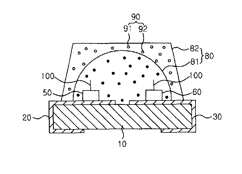
[0043]FIG. 1 is a sectional view showing the light emitting device according to the present invention.

[0044]Referring to the figure, the light emitting device comprises a substrate 10 and first and second electrodes 20 and 30 formed on the substrate 10. A light emitting diode 50 for emitting ultraviolet ray is mounted on the first electrode 20, and first and second phosphors 91 and 92, which are excited by the ultraviolet ray to emit blue and green lights having peak wavelengths longer than the wavelength of the excitation light, are arranged over the first light emitting diode 50.

[0045]A second light emitting diode 60 is mounted on the second electrode 30, and emits red light different in wavelength from lights emitted from the first and second phosphors 91 and 92.

[0046]The first and second light emitting diodes 50 and 60 are commonly and electrically connected to a third electrode (not shown) through wires 100.

[0047]A molding portion 80 for encapsulating the first and second light...

second embodiment

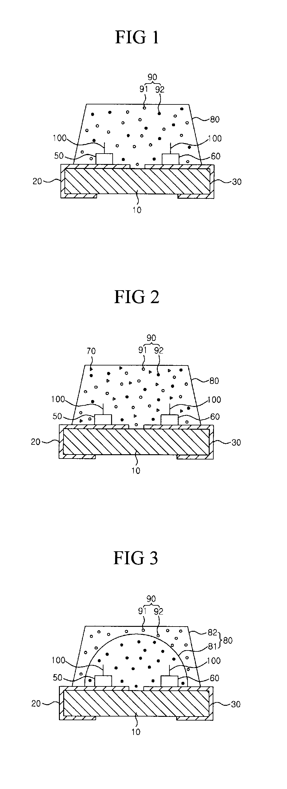
[0058]FIG. 2 is a sectional view showing the light emitting device according to the present invention.

[0059]Referring to this figure, the light emitting device comprises a substrate 10 and first and second electrodes 20 and 30 formed on the substrate 10. A light emitting diode 50 for emitting ultraviolet ray is mounted on the first electrode 20, and first and second phosphors 91 and 92 which are excited by the ultraviolet ray to emit blue and green lights having peak wavelengths longer than the wavelength of the excitation light are arranged over the first light emitting diode 50.

[0060]A second light emitting diode 60 is mounted on the second electrode 30, and emits red light different in wavelength from lights emitted from the first and second phosphors 91 and 92.

[0061]A molding portion 80 for encapsulating the first and second light emitting diodes 50 and 60 is provided on the substrate 10, and the first phosphor 91 for emitting blue light, the second phosphor 92 for emitting gree...

third embodiment

[0068]FIG. 3 is a sectional view showing the light emitting device according to the present invention.

[0069]Referring to this figure, the light emitting device comprises a substrate 10 and first and second electrodes 20 and 30 formed on the substrate 10.

[0070]A light emitting diode 50 for emitting ultraviolet ray is mounted on the first electrode 20, and first and second phosphors 91 and 92 which are excited by the ultraviolet ray to emit blue and green lights having peak wavelengths longer than the wavelength of the excitation light are arranged over the first light emitting diode 50.

[0071]A second light emitting diode 60 is mounted on the second electrode 30, and emits red light different in wavelength from lights emitted from the first and second phosphors 91 and 92. This is mostly identical with the constitutional features of the first embodiment, and therefore, the overlapping specific descriptions will be omitted.

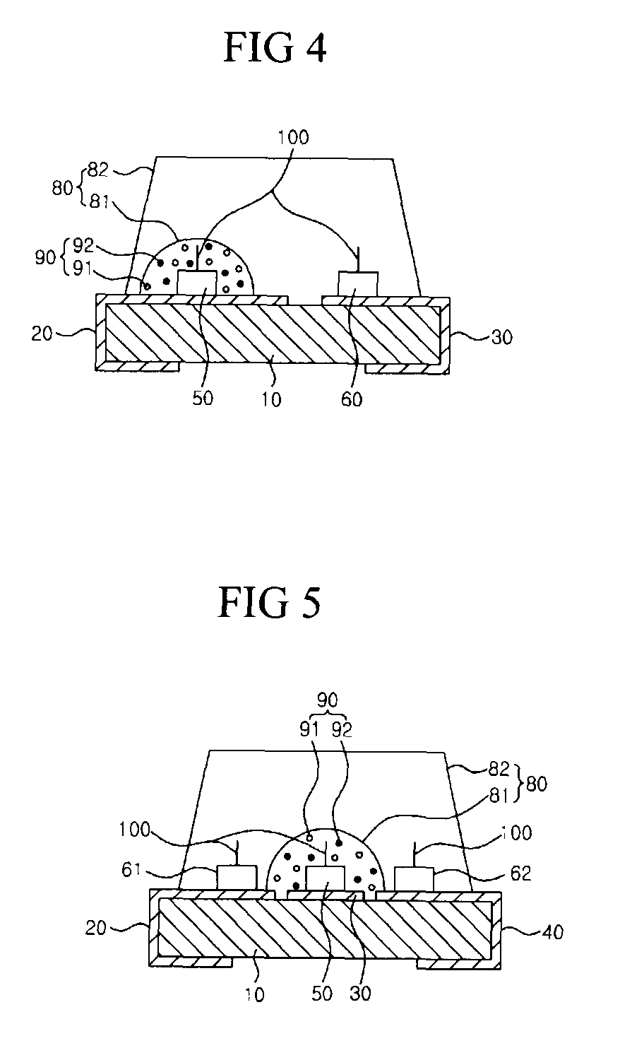
[0072]The light emitting device according to the this embodiment...


PUM


Abstract

The present invention provides a light emitting device, comprising a first light emitting diode for emitting light in an ultraviolet wavelength region; at least one phosphor arranged around the first light emitting diode and excited by the light emitted from the first light emitting diode to emit light having a peak wavelength longer than the wavelength of the light emitted from the first light emitting diode; and at least one second light emitting diode for emitting light having a wavelength different from the peak wavelength of the light emitted from the phosphor. According to the present invention, there is provided a white light emitting device, wherein using a light emitting diode for emitting light different in wavelength from light that is ex-cititively emitted from the phosphor, an excitation light source, i.e., light in the ultraviolet region for exciting the phosphor is effectively used, thereby improving energy conversion efficiency and improving reliability.

Description

CROSS REFERENCE TO RELATED APPLICATIONS[0001]This application is the National Stage of International Application No. PCT / KR2007 / 004066, filed Aug. 24, 2007, and claims priority from and the benefit of Korean Patent Application No. 10-2006-0082501, filed on Aug. 29, 2006, which are both hereby incorporated by reference for all purposes as if fully set forth herein.BACKGROUND OF THE INVENTION[0002]1. Field of the Invention[0003]The present invention relates to a light emitting device, and more particularly, to a light emitting device in which an energy conversion efficiency can be improved by using an ultraviolet light emitting diode as an excitation source of a phosphor.[0004]2. Discussion of the Background[0005]A light emitting diode (LED) refers to a device for emitting light through recombination of minority carriers (electrons or holes) as a compound semiconductor having p-n junction structure. Since the light emitting diode has characteristics of low power consumption, long life...

Claims


Application Information

Patent Timeline
Patent Type & Authority Patents(United States)
IPC IPC(8): H01L33/50
CPCC09K11/7734C09K11/7792H01L25/0753H01L2224/48H01L33/50Y02B20/181Y02B20/00C09K11/77922C09K11/77342
Inventor LEE, SANG MINCHOI, HYUCK JUNGKIM, MI HAE
Owner SEOUL SEMICONDUCTOR
Why Eureka
Try Eureka