[0004]Considering the aspects of a high efficiency, the invention proposes, according to claim 1, a collector tube which reduces the
stagnation temperature. According to the present invention, the
heat transfer medium is not flowing through a U-shaped tube but directly along the inner wall of the absorber tube. This eliminates
thermal contact resistance between absorber tube,
heat conducting sheet and U-shaped tube, and the collector efficiency is raised. In addition, it minimizes the volume of the to-be-heated
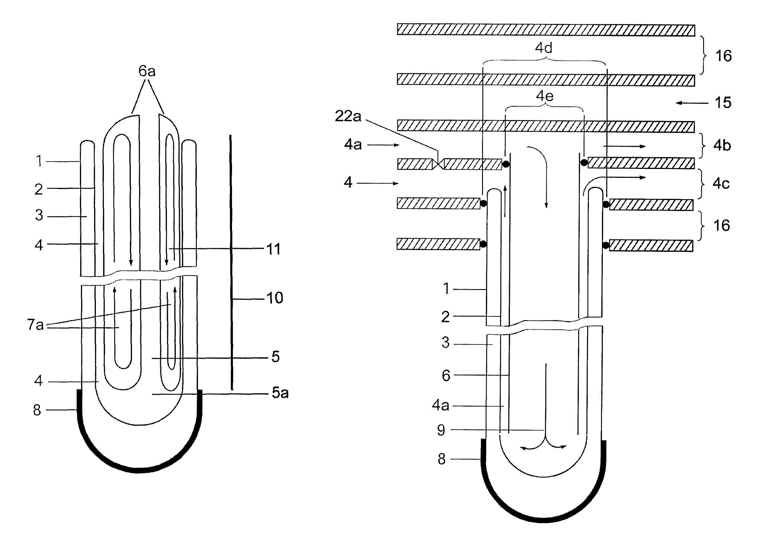
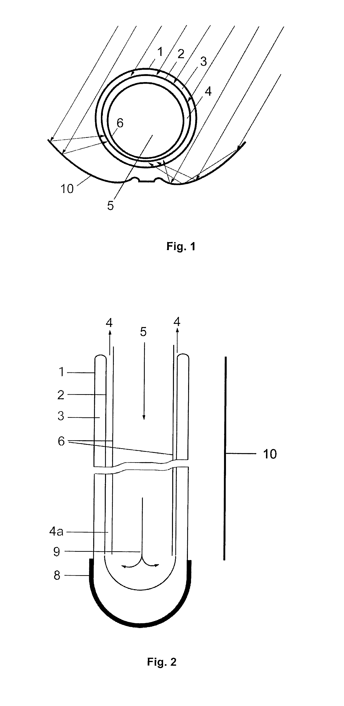
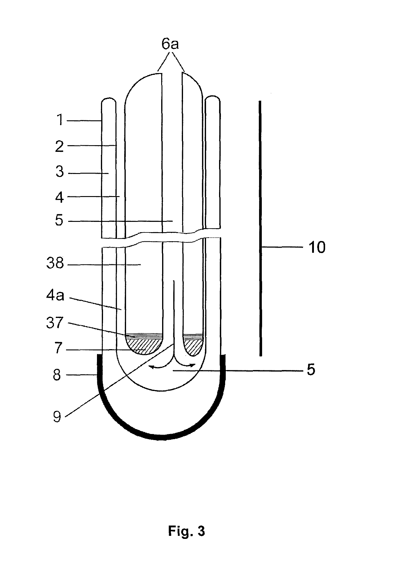
heat transfer medium, to reduce the reaction time of the collector. For this reason, every collector tube has a coaxial tube inside its cavity. The coaxial tube separates the entering cold heat transfer medium from the heated heat transfer medium. The cold heat transfer medium flows inside the coaxial tube to the lower end of the collector tube and flows back between the outside of the coaxial tube and the inner surface of the absorber tube for thermal absorption. In cross-section, the coaxial tube is eccentrically located in the cavity of the collector tube. The eccentricity of the coaxial tube is oriented towards the light-averted side of the collector tube. Thus, the volume of the to-be-heated heat transfer medium decreases at the light-averted side and at the same time increases at the light-facing side. That way, the heat transfer medium is being heated up on the light-averted side, in
spite of low light
radiation, as quickly as on the light-facing side. The reflector may be sized smaller in proportion to the
diameter of the tube. In diffuse light conditions, the smaller reflector has only minor effects, but it ensures that the
stagnation temperature rises less under direct normal
radiation.
[0007]The variable
thermal conductivity of the coaxial tube can also be reached in a further embodiment of the invention by using materials like bimetals or materials with shape memory which can create thermal bridges in the double-walled coaxial tube. Also materials are possible that show a variable thermal
conductivity as a result of changes in their molecular structure. A further option according to the invention is that a double-walled coaxial tube is used which is provided with special
layers for emission and absorption of heat radiation. The outer tube of the double-walled coaxial tube will therefore be applied with a variable selective
coating on the inner surface. This coating emits no or only little heat radiation at low temperatures, as prevailing in normal operation of the collector. Only at high temperatures, like in case of stagnation, or when exceeding a limit temperature, the variable selective coating is able to radiate heat. To avoid reflection of the inner coaxial tube, an absorption coating can be applied on the outside of the inner coaxial tube. After absorption, the heat will be transferred through the inner coaxial tube onto the cold
water reservoir. Inner and outer coaxial tube are preferably connected with each other at the ends, so that a cavity is created. Since the emission and absorption coatings are inside the cavity of the coaxial tube, they do not come in contact with the heat transfer medium and are therefore protected from abrasion, debris and
chemical transformation. The position of the inner coaxial tube in the outer coaxial tube can be concentric or eccentric.
Ceramic coatings with an absorption maximum in the
infrared range of the
light spectrum are particularly suitable as absorption coating of the inner coaxial tube. To avoid heat transfer as a result of
thermal conduction also at low temperatures, the cavity of the coaxial tube can be evacuated.
[0011]In case of stagnation, when no heat transfer medium circulates in the collector, the heat removal from the outer and the inner coaxial tubes will also be interrupted. The heat is then transferred through the walls of the coaxial tube from layer to layer into the inside of the coaxial tube to the cold
water reservoir. By removing the heat from the absorber tube to the cold
water reservoir, an overheating will be avoided.
[0013]The big
diameter of the coaxial tubes provides advantages for an easier ventilation, since air bubbles can rise in the coaxial tube without being carried away by the flow of the heat transfer medium. This uncomplicated way of venting provides the opportunity to connect the collector with a drainback
system, in which the heat transfer medium is drained when the
system stagnates. This offers another possibility to cool down the heat transfer medium overnight. The
advantage is also that at very low temperatures during the winter the heat transfer medium flows into the collector with a relatively high temperature level (
room temperature) and no energy is needed to raise the temperatures of the heat transfer medium from minus up to this level.
[0019]A particularly advantageous design of a segment for a collector tube as well as for a coaxial tube is made of heat-resistant plastic, produced by injection molding. This production process permits low piece costs, uses also the segmentation of the manifolds, since that way the unequal
thermal expansion within one component can be compensated the easiest way.
