Reactors having varying cross-section, methods of making same, and methods of conducting reactions with varying local contact time

a technology of chemical reactors and cross-sections, applied in physical/chemical process catalysts, laboratory glassware, instruments, etc., can solve the problems of low selectivity of desired products, lack of uniform temperature in the axial direction, and fast catalyst deactivation, so as to improve the coupling between chemical reaction and heat transfer, linear velocity or local contact time can be gradually increased or decreased, and the temperature distribution is uniform. uniform

Active Publication Date: 2012-06-26
BATTELLE MEMORIAL INST
View PDF30 Cites 5 Cited by
  • Summary
  • Abstract
  • Description
  • Claims
  • Application Information

AI Technical Summary

Benefits of technology

[0012]Various embodiments of the invention can provide numerous advantages including one or more of the following. The coupling of chemical reaction and heat transfer can be improved, which may result in more uniform temperature distribution in the catalyst bed. Linear velocity or local contact time can be gradually increased or decreased from the inlet to the outlet of the reaction section. Temperature distribution and local conversion profiles are flattened, which can be critical in improving product selectivity and prolonging catalyst life. Reactor productivity can be improved because the uniform temperature profile permits the reactor to be operated with a larger part of the reactor volume near its optimal temperature.
[0013]Without wishing to be bound by a particular explanation or theory, it is believed that the improvement in the properties of the inventive reactors and methods, as compared with prior art, may be related to the following aspects. In the channel reactor according to the present invention, the heat generation rate is lowered in the prospective hot spot area, while heat is conducted away in an efficient manner. Conversely, the heat generation rate is increased in the cold spot areas so as to maintain temperature. A narrow inlet area decreases the reaction extent by increasing the linear velocity or reducing contact time, and, thus, for exothermic reactions, the narrow inlet area reduces the heat generated in that area. The narrow inlet area can also increase the heat-removing rate because of the short distance for heat transfer. On the other hand, the extent of reaction (extent of conversion) is increased in the wider section of the bed because of the lower linear velocity or longer contact time, while the heat conduction rate may be reduced due to the increase of bed thickness. As a result, the reaction heat may be forced to spread out over the whole reactor bed, which is believed to improve the uniformity of temperature distribution.
[0014]The impact of the present invention is qualitatively different in microchannel reactors. Microchannel reactors have improved heat and mass transfer efficiency. Therefore, reactions typically occur in a kinetically-controlled regime. In microchannels, improving the uniformity of temperature distribution in the flow direction improves greatly the uniformity of temperature distribution in the whole bed. It has been surprisingly discovered that superior modeling results, such as better temperature control, occur in reactors and methods utilizing the microchannel design described herein. It is believed that comparable advantages are not available in apparatus with conventional flowpaths.

Problems solved by technology

Temperature lacks uniformity in the axial direction (flow direction) and reactant concentrations are typically high in the inlet zone.
As a result, the integrated effects can cause high reaction rates in the inlet zone for highly exothermic reactions, as well as local hot spots, resulting in fast catalyst deactivation and low selectivity of desired products.
On the other hand, for endothermic reactions, this can cause cold spots and poorer catalyst utilization.

Method used


Image

  • Reactors having varying cross-section, methods of making same, and methods of conducting reactions with varying local contact time
  • Reactors having varying cross-section, methods of making same, and methods of conducting reactions with varying local contact time
  • Reactors having varying cross-section, methods of making same, and methods of conducting reactions with varying local contact time

Examples


examples

Model Conditions and Catalyst

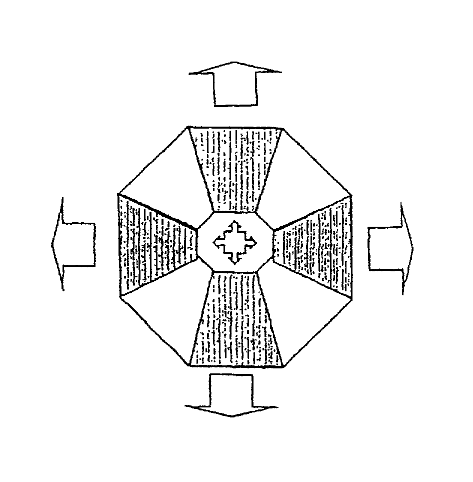
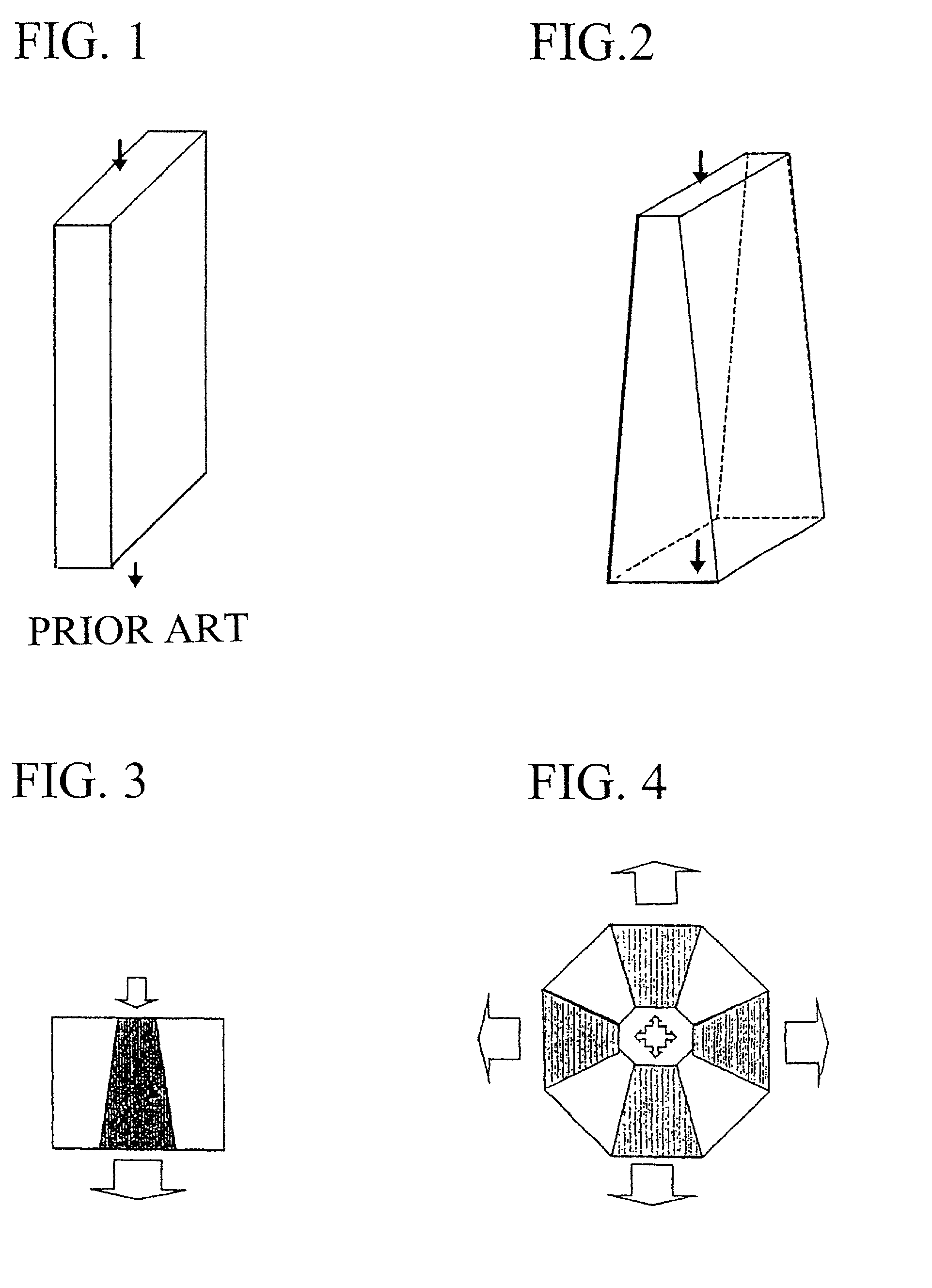
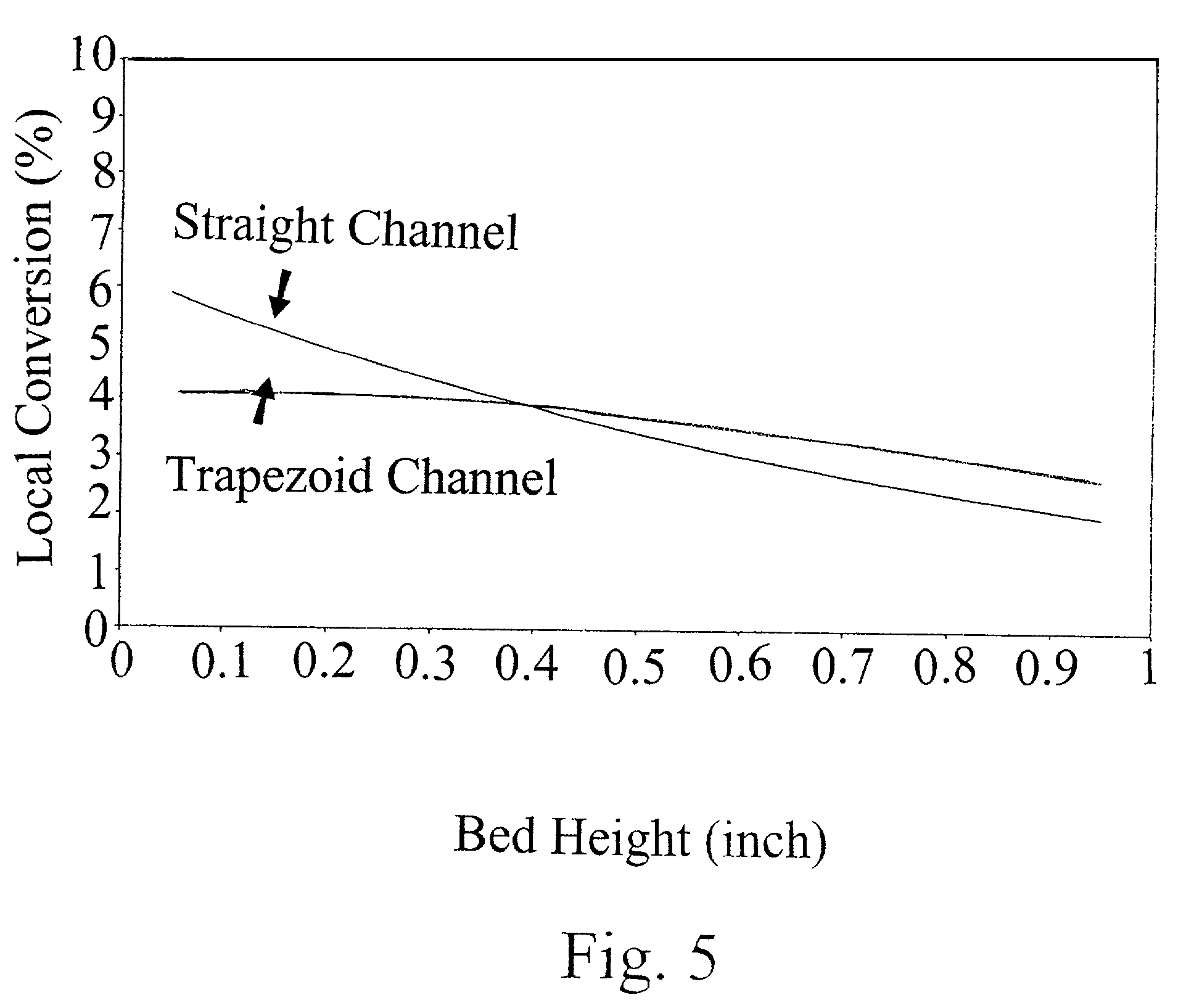
[0042]Since Fischer-Tropsch synthesis (“FTS”) is a highly exothermic reaction, it is a good model system to validate the concept of the present invention. FTS generally requires temperature control in a narrow range to avoid excessive methane production and catalyst deactivation. Microchannel reactors with straight and trapezoidal channel geometries (table 1) with jacketed active cooling system can be employed to collect reaction kinetics in various process conditions. Porous media containing catalytic materials are packed in the microchannel reactors. The catalysts are supported by packing thin layers of quartz wool and held by metal foams in both ends in a straight channel with the dimensions described in Table 1. Catalyst loading amount is 0.22 gram. The catalyst for this experiment can be prepared as follows. First, acidic gamma-alumina support powder (Engelhard) is ground and sieved to between 80- and 100-mesh (150 to 180-micron), and calcined (stab...


PUM

PropertyMeasurementUnit
heightaaaaaaaaaa
widthaaaaaaaaaa
heightaaaaaaaaaa

Abstract

The present invention provides methods of conducting chemical reactions in a reaction channel that has an varying cross-sectional area such that a chemical reactant or reactants experience varying local contact time as the reactant(s) flow through the channel. The invention also provides reactors having reaction channels with varying cross-sectional areas. In a particularly preferred embodiment, the reaction channel section has a trapezoidal shape that becomes broader from the inlet toward the outlet.

Description

FIELD OF THE INVENTION[0001]The invention relates to chemical reactors comprising a reaction microchannel and to methods for reacting materials in the reactors. The invention also relates to reactors having multiple channels emanating from a common inlet and to methods for reacting materials in these reactors.BACKGROUND OF THE INVENTION[0002]In conventional chemical reactors, the reaction chamber containing the catalyst has straight walls in the direction of the flow. Thus, the reaction chamber forms a channel that has a constant cross-section along the flow direction over the length of the chamber between an inlet and an outlet. The conventional reactors described here include flow through type catalytic and non-catalytic reactors. Catalytic reactions are either heterogeneous or homogeneous.[0003]Straight channel reactors have several drawbacks. For non-zero order homogeneous or heterogeneous reactions, temperature varies considerably from point to point in the catalyst bed, in par...

Claims


Application Information

Patent Timeline
Patent Type & Authority Patents(United States)
IPC IPC(8): B01J8/00B01J8/02B01J19/24B01J19/00B01L3/00
CPCB01J19/0093B01J2219/00835Y10T436/2575B01L3/5027B01J2219/0086
Inventor WANG, YONGCAO, CHUNSHEKIMBLE, JAMES B.SILVA, LAURA J.
Owner BATTELLE MEMORIAL INST
Why Eureka
Try Eureka