
Drug eluting balloon

a balloon and eluting technology, applied in balloon catheters, dilators, surgery, etc., can solve the problems of blood vessel walls being disturbed or injured, drawbacks during use, and potential trauma or injury to the expanded passage or vessel, so as to reduce the amount of agents, minimize and eliminate edge effects, and limit systemic exposure of patients

Active Publication Date: 2012-07-03
COOK MEDICAL TECH LLC
View PDF6 Cites 9 Cited by
  • Summary
  • Abstract
  • Description
  • Claims
  • Application Information

AI Technical Summary

Benefits of technology

The present invention provides a medical balloon assembly for treatment of patients. The assembly includes an inner and outer balloon member, with the outer balloon member being more compliant than the inner balloon member. The outer balloon member is enveloped by the inner balloon member and is biased towards it when inflated. The outer balloon member can have one or more holes or ports for elution of medicament. It can be made of a porous material or a rubber-based material. The inner balloon member can be made of the same material as the outer balloon member, or a different material. The assembly can also include a catheter element for supplying inflation fluid and treatment fluid between the inner and outer balloon members. The technical effects of the invention include improved delivery of medicament to a patient, reduced blood loss, and improved valving system.

Problems solved by technology

Some drawbacks can be encountered during their use, however.
For example, when a balloon is expanded to open a body passage or vessel lumen, the expanded balloon may cause potential trauma or injury to the expanded passage or vessel.
Likewise, when a device is introduced into and manipulated through the vascular system of a patient, the blood vessel walls can be disturbed or injured.
Clot formation or thrombosis often results at the injured site, causing stenosis (closure) of the blood vessel.
Moreover, if the medical device is left within the patient for an extended period of time, thrombus can form on the device itself, again causing stenosis.
As a result, the patient is placed at risk of a variety of complications, including heart attack, pulmonary embolism, and stroke.
Thus, the use of such a medical device can entail the risk of precisely the problems that its use was intended to ameliorate.
When medical devices such as stents and, in particular, coated stents are implanted in a vessel lumen, edge effect trauma can occur to the tissue at and beyond the ends of the implanted stent.
This trauma or injury can be the result of the implanted stent causing injury to the vessel wall.
Should the stent be coated or include a therapeutic agent, the therapeutic agent can possibly cause injury to the tissue extending beyond the ends of the stent.
Furthermore, delivery agents such as polymers and the like used to deliver the treatment agent can also cause this edge effect reaction to the tissue extending beyond the ends of the implanted stent.
However, it is to be understood that regardless of the cause of the trauma or injury to the vessel wall, the tissue will typically react with the proliferation of smooth muscle cells and the like, thereby creating an adverse reaction and subsequent closure or stenosis of the vessel.
Unfortunately, the durable application of bioactive materials to stents and the like, sufficient for such introduction to successfully occur, is often problematic.
Moreover, as explained above, the stent itself can cause trauma to the vessel walls, leading in some cases to thrombosis or restenosis.
This inevitably results in some blood loss and collection in the catheter assembly.

Method used


Image

  • Drug eluting balloon
  • Drug eluting balloon
  • Drug eluting balloon

Examples


Embodiment Construction

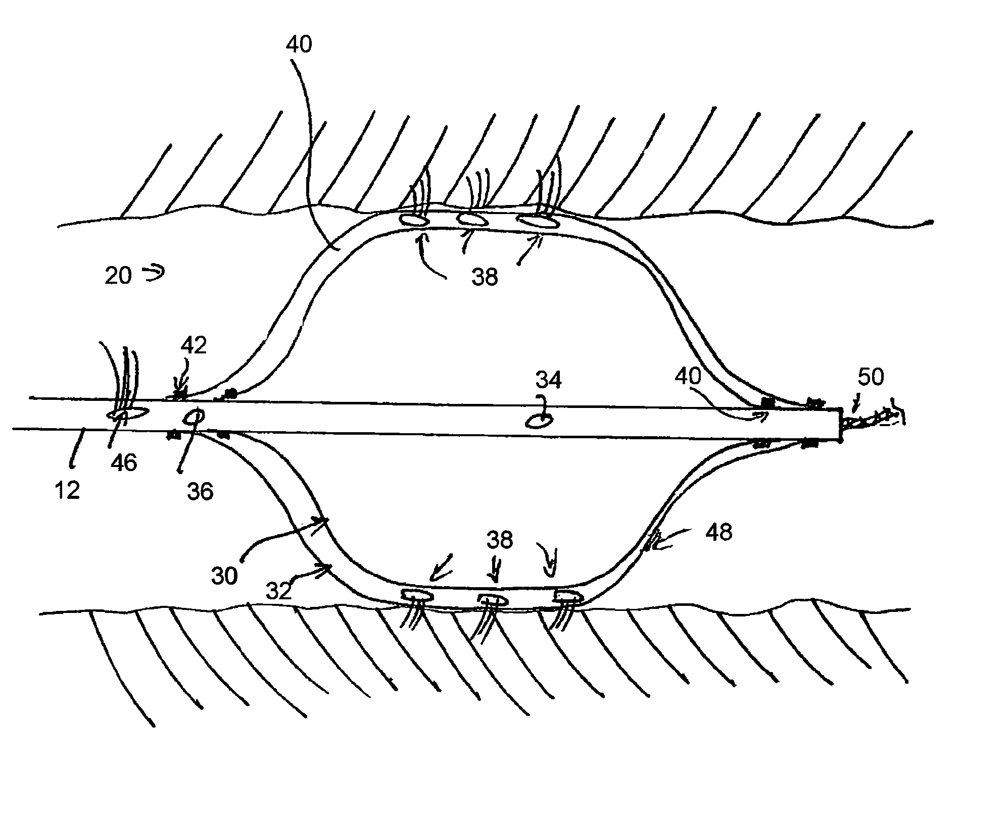
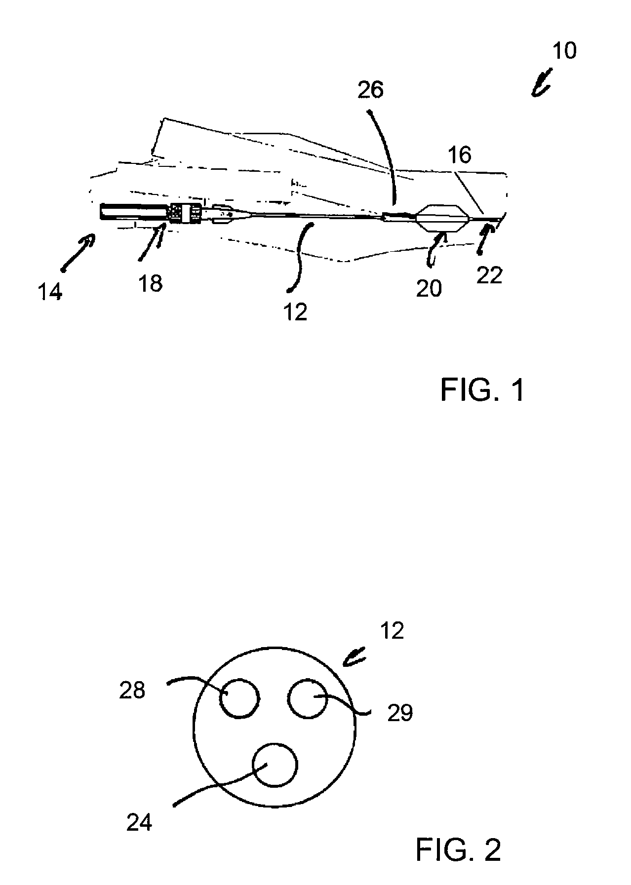
[0040]Referring to FIG. 1, there is shown in schematic form an example of balloon catheter assembly 10. The assembly includes an elongate catheter 12 of such a length that the proximal end 14 of the assembly 10 remains outside the patient even when the distal end 16 is at the treatment site within the patient.

[0041]The proximal end 14 is provided with external manipulation elements 18 of a type well known in the art, including one or more handles for use by the surgeon in moving and placing the catheter, connectors for connecting the catheter to a source of medicaments or other fluids, balloon inflation equipment and so on. The proximal end also includes a connector port for the passage of a guide wire therethrough as well as other elements conventionally found in such assemblies.

[0042]At or adjacent the distal end of the assembly 10 there is provided an inflatable balloon assembly 20, described in further detail below. At the tip of the distal end 16, there is advantageously provid...


PUM


Abstract

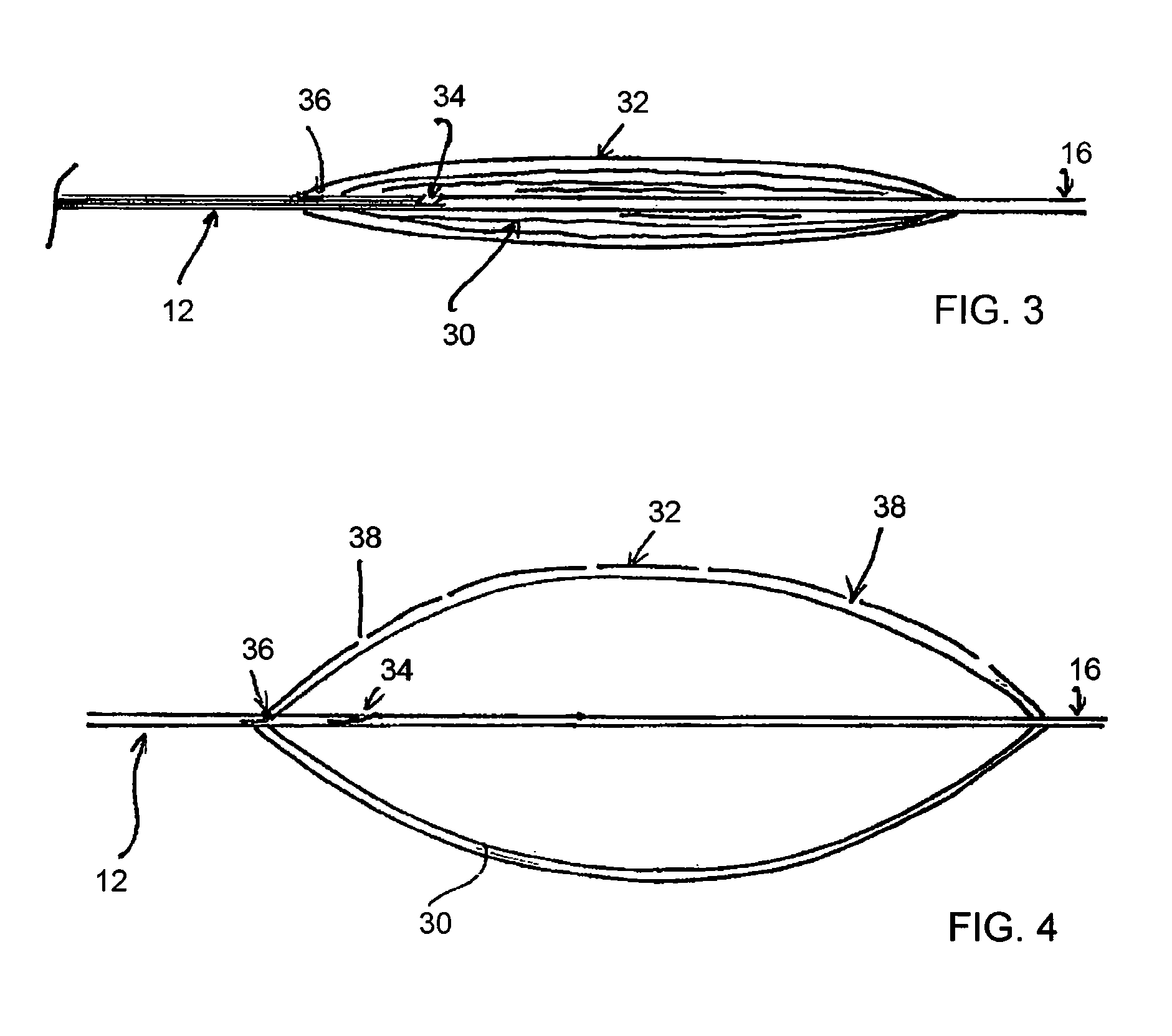
There is disclosed a drug eluting balloon catheter assembly provided with a balloon formed of an inner balloon member of non-compliant material and an outer balloon member of a compliant material and which is provided with holes therein for eluting a drug or other fluid. In use, the outer balloon member is biased by contraction onto the inner balloon member thereby keeping the holes therein normally sealed closed and minimizing dead space in the device.

Description

[0001]CROSS-REFERENCE TO RELATED APPLICATIONS[0002]This application is a U.S. nationalization of PCT application No. PCT / US2008 / 075944, filed Sep. 11, 2008, and claims priority to U.S. Provisional Application Ser. No. 60 / 993,361, filed Sep. 12, 2007.FIELD OF THE INVENTION[0003]The present invention relates to a human or veterinary medical device and, more particularly, to a balloon designed to elute a drug, bioactive agent, therapeutic agent or diagnostic agent. The present invention also relates to a catheter assembly including such a balloon.BACKGROUND OF THE INVENTION[0004]It has become common to treat a variety of medical conditions by temporarily or permanently introducing a coated medical device, and, in particular, a coated medical implanted device partly or completely into the esophagus, trachea, colon, biliary tract, urinary tract, vascular system or other location within a human or veterinary patient. Many treatments of the vascular or other systems entail the introduction...

Claims


Application Information

Patent Timeline
Patent Type & Authority Patents(United States)
IPC IPC(8): A61M29/00A61F2/958
CPCA61M25/10A61M2025/1013A61M2025/105A61M2025/1072
Inventor CHRISTIANSEN, FRANK K.
Owner COOK MEDICAL TECH LLC
Learn More