
Optically compensatory film, polarizing plate and liquid-crystal display

a liquid crystal display and polarizing plate technology, applied in the direction of polarizing elements, instruments, transportation and packaging, etc., can solve the problems of difficult formation of cellulose acylate films having a small re change depending on the angle, the change of optical characteristics in the width direction and the length direction, etc., to achieve small change in display characteristics, small optical anisotropy, and low wavelength-dependent distribution of optical anisotropy

Active Publication Date: 2012-07-24
FUJIFILM CORP
View PDF18 Cites 0 Cited by
  • Summary
  • Abstract
  • Description
  • Claims
  • Application Information

AI Technical Summary

Benefits of technology

[0011]A first object of the present invention is to provide a liquid-crystal display device having a small change in the display characteristics against changes in ambient temperature and humidity. A second object of the present invention is to provide a cellulose acylate film which has a small optical anisotropy (Re, Rth) (i.e., is substantially optically isotropic) and has a low level of wavelength-dependent distribution of optical anisotropy (Re, Rth). A third object of the present invention is to provide an optically-compensatory film, a polarizing plate, and a liquid-crystal display device including a cyclic polyolefin film which can exhibit optical anisotropy and a cellulose acylate film which has a low level of optical anisotropy (Re, Rth) (i.e., is substantially optically isotropic).
[0012]A fourth object of the present invention is to demonstrate that an optical member, such as an optically-compensatory film, a polarizing plate, or the like, which is formed of a cellulose acylate film having a low level of optical anisotropy and a low level of wavelength-dependent distribution, has excellent viewing angle characteristics, and to provide a liquid-crystal display device using the same.
[0013]By using a cellulose acylate film having a low level of optical anisotropy and a low level of wavelength-dependent distribution as a protective film for a polarizing plate, the optical characteristics of the polarizing plate can be improved. In the case where such a cellulose acylate film is used for a support for an optically-compensatory film, the optical performance of the optically-compensatory film itself can be exploited. By using such a polarizing plate or optically-compensatory film for a liquid-crystal display device, the contrast and the hue can be improved.
[0015]Specifically, a film having a high level of optical anisotropy is formed of the cycle polyolefin film, so that the optical characteristics are unlikely to change against changes in ambient temperature and humidity, and a film for protecting the polarizer is formed of the above-described cellulose acylate film, which has a considerably suppressed level of optical anisotropy and a high level of adhesiveness with polyvinyl alcohol of the polarizer and has a smaller change in display performance against changes in ambient temperature and humidity than that of a plain tack film. By using such a combination of films for a liquid-crystal display device, the contrast and the hue can be improved.

Problems solved by technology

However, the heat fusion film formation has the problem that the optical characteristics in the width direction and the length direction (the retardation direction and the optical axis direction) change.
Cellulose acylate films with a reduced in-plane Re are conventionally available, but it has been difficult to form a cellulose acylate film having a small Re change depending on the angle, i.e., having a small Rth.
However, these conventionally known compounds are not considered to have a sufficient effect of lowering the optical anisotropy of cellulose acylate films.

Method used


Image

  • Optically compensatory film, polarizing plate and liquid-crystal display
  • Optically compensatory film, polarizing plate and liquid-crystal display
  • Optically compensatory film, polarizing plate and liquid-crystal display

Examples


example 1

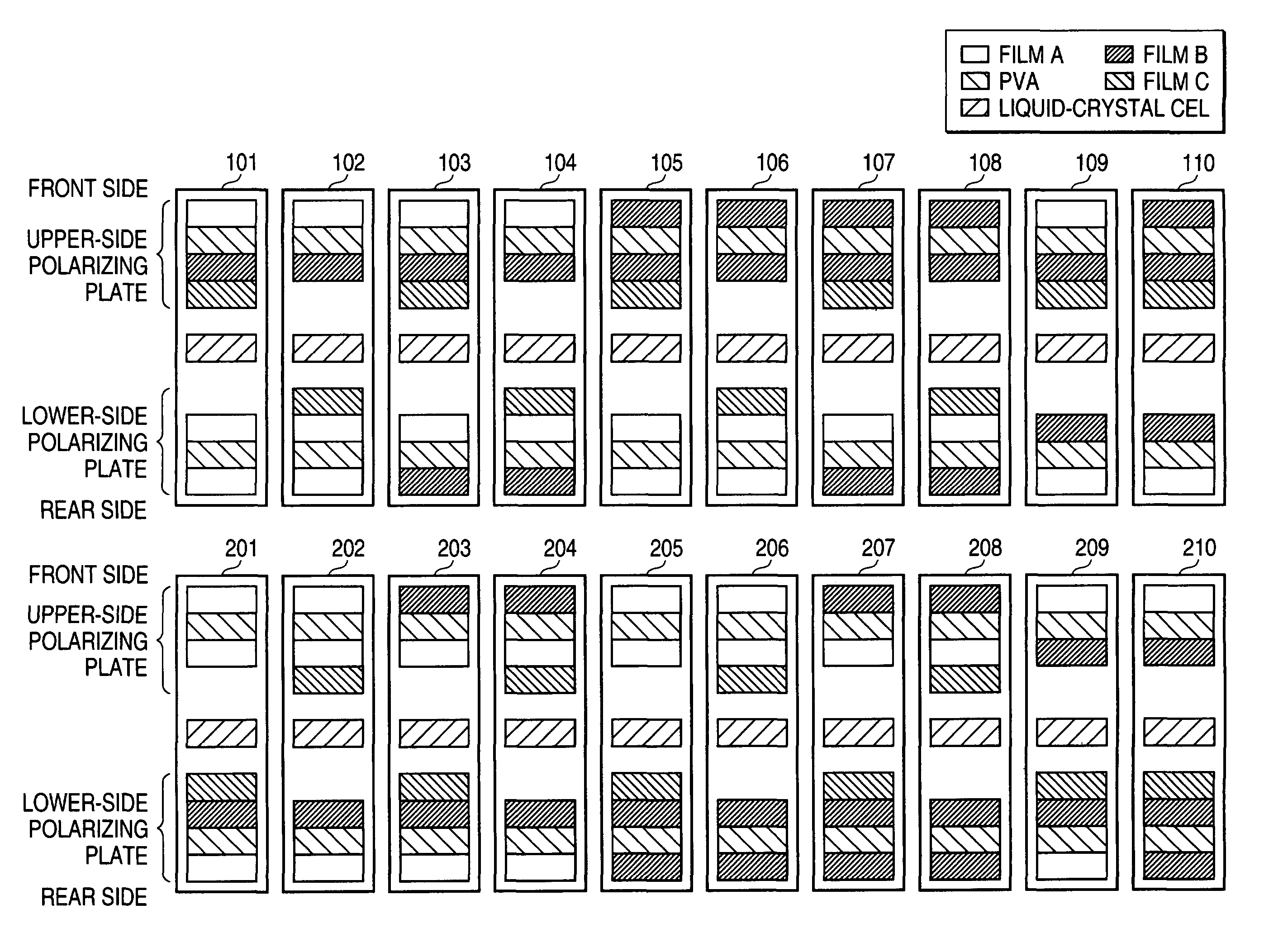
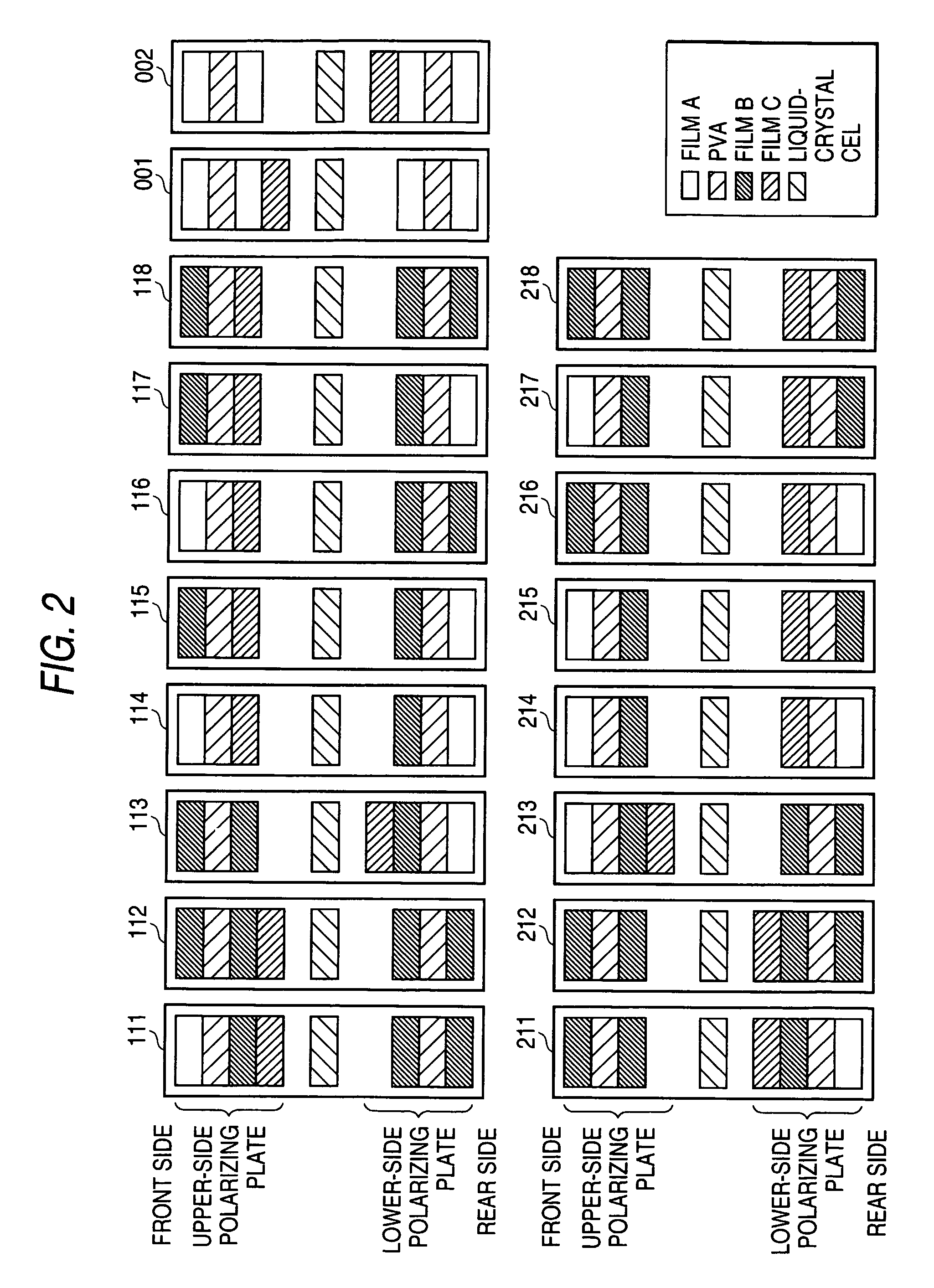
[0400]Exemplary structures of liquid-crystal display devices to which the present invention is applied are shown in FIGS. 1 and 2. Film A represents a commercially available cellulose acetate film, film B represents the cellulose acetate film of the samples 101 to 104 formed in the film formation example 4, PVA represents a polarization film described below, and film C represents a cyclic polyolefin film formed in the film formation examples 1 to 3.

[0401]In this example, a VA-mode liquid-crystal display device is used, but the polarizing plate and the optically-compensatory film using the film of the present invention and the uses of the structure thereof are not limited by the operation mode of the liquid-crystal display device.

(Production of a Polarizing Plate)

[0402]The cellulose acetate film sample 101 obtained in the film formation example 4 and a commercially available cellulose acetate film (TF80UL, 80 μm) were immersed in an aqueous solution of 1.5N sodium hydroxide at 55° C....

example 2

[0414]Structure 201 in FIG. 1 was obtained in substantially the same manner as in example 1, except that the upper-side polarizing plate was located on the lower side (the backlight side) and the lower-side polarizing plate was located on the upper side (the viewer side).

[0415]As a result of viewing the resultant liquid-crystal display device, it was found that black display which was neutral in the front direction and the viewing angle direction was realized. As a result of measuring the viewing angle (the range in which the contrast is 10 or more and the black display is not inverted) using a measuring apparatus, it was found that the viewing angle was satisfactory at 80° or more both in the left-right direction and the top-bottom direction.

[0416]This liquid-crystal panel was subjected to an ambient-humidity change (10% RH, 80% RH). Even after 1 week, the hue of the black display and the viewing angle were both almost the same as those measured at 60% RH. No significant reduction ...

example 3

[0421]Structures 102 to 108 and 202 to 208 in FIG. 1 were each obtained by substantially the same method as that of examples 1 and 2, and the viewing angle and the hue of the black display were observed. Substantially the same results as those of examples 1 and 2 were obtained. Good display visibility was provided, and no significant reduction in the liquid-crystal display visibility was recognized even by the ambient humidity change.


PUM

PropertyMeasurementUnit
thicknessaaaaaaaaaa
Tgaaaaaaaaaa
Tgaaaaaaaaaa

Abstract

An optically-compensatory film comprising: a cyclic polyolefin film satisfying expression (I); and a cellulose acylate film satisfying expressions (II) and (III), or a liquid-crystal display device comprising at least one cyclic polyolefin film satisfying expression (I) and at least one cellulose acylate film satisfying expressions (II) and (III):35≦Re(630)≦350 and 70≦Rth(630)≦400,  (I)0≦Re(630)≦10 and |Rth(630)|≦25, and  (II)|Re(400)−Re(700)|≦10 and |Rth(400)−Rth(700)|≦35,  (III)wherein Re(λ) represents an in-plane retardation value (unit: nm) at a wavelength of λ nm; and Rth(λ) represents a thickness-direction retardation value at a wavelength of λ nm.

Description

[0001]This application is a 371 national stage of PCT / JP2006 / 300785 filed Jan. 13, 2006.TECHNICAL FIELD[0002]The present invention relates to an optically-compensatory film, a polarizing plate, and a liquid-crystal display device. Specifically, the present invention relates to a cyclic polyolefin optical biaxial phase retardation film used therefor and a cellulose acylate film useful for a liquid-crystal display device, and also optical members using the same, such as an optically-compensatory film, a polarizing plate, and the like, and a liquid-crystal display device using the same.BACKGROUND ART[0003]A polarizing plate is typically produced by attaching a film mainly formed of cellulose triacetate as a protective film on both sides of a polarization film which is formed of iodine or a dichroic dye aligned and adsorbed to polyvinyl alcohol. Cellulose triacetate has features of being high in rigidity, frame resistance, and optical isotropy (low retardation value), and is widely used...

Claims


Application Information

Patent Timeline
Patent Type & Authority Patents(United States)
IPC IPC(8): G02F1/13363
CPCC08L1/10C08L1/12G02F1/13363G02B5/30Y10T428/1041G02F2202/40G02F2413/01Y10T428/1036G02F2201/50C09K2323/03C09K2323/031
Inventor OHGARU, IKUKOOHTANI, SUMIO
Owner FUJIFILM CORP
Learn More