Intumescent fire door edge system

a fire door and intumescent technology, applied in the field of intumescent materials and components, can solve the problems of increasing the gap between the edges, reducing the creep of the intumescent layer, and charging of the wood edge, so as to and reduce the creep of the intumescent layer. the effect of high creep susceptibility

Inactive Publication Date: 2012-07-31
LANCOTEK PROD
View PDF19 Cites 10 Cited by
  • Summary
  • Abstract
  • Description
  • Claims
  • Application Information

AI Technical Summary

Benefits of technology

[0011]When a door is exposed to fire, hot combustion gases can flow through gaps formed between the edges of the door and a surrounding doorframe. Exposure to these hot combustion gases can cause the edges of the door to char and / or burn faster than the core of the door. Charring and burning of the edges of the door can increase the size of the gap between the edges and the surrounding frame, which can increase the flow of combustion gases around the door. If a sufficient flow of combustion gases passes around the edges of a door, a fire may spread past the door even if the fire does not consume the core of the door. Inhibiting the flow of combustion gases around the edges of a door can inhibit the spread of fire past the fire door.
[0014]The intumescent strip described herein can be affixed to the edges of a fire door and is expandable in a primary direction in order to create a gas seal between a fire door and a surrounding door frame, and a secondary direction to cover, and provide some thermal protection to, adjacent portions of the fire door and / or door frame. The intumescent strip includes two strips of non-intumescent material sandwiching an intumescent layer.
[0015]The intumescent layer can be formed from a plurality of expandable, intumescent particles suspended in a thermoplastic material. The intumescent particles can be formed from any suitable intumescent material, including known materials that are only expandable in a single direction, such as expandable graphite. Orienting the individual particles of intumescent material in different orientations within the thermoplastic material enables the layer to be expandable in at least the primary and secondary directions, even if each intumescent particle is only expandable in a single direction. Encapsulating relatively small intumescent particles within a thermoplastic matrix can insulate the intumescent particles from the surrounding atmosphere, which may inhibit degradation of the intumescent material. The thermoplastic can be selected to exhibit relatively little creep at room temperature (when compared to Palusol™), which can provide an intumescent layer that is generally resistant to creep at room temperature, even if the intumescent material used to form the particles has a high creep susceptibility. The thermoplastic material is selected to have a melting temperature that is lower than an activation temperature of the intumescent particles, so the plastic can be melted without activating the expansion of the intumescent particles. This enables the mixture of intumescent particles and thermoplastic material to be extruded, and may allow the thermoplastic material to melt and flow around portions of the fire door prior to, and during the activation of the intumescent particles.
[0016]The non-intumescent strips can be connected by a plurality of fasteners that extend through the intumescent layer. The fasteners are operable to at least partially resist expansion of the intumescent strip in the secondary direction so as to limit the flow and expansion in the secondary direction (optionally a fraction of the extend of the primary expansion, for example about 10% or less). The plurality of fasteners act as a variable resistance to flow in the secondary direction. This resistance to flow in the secondary direction can vary from little resistance to complete elimination of flow in the secondary direction. The resistance to expansion in the primary direction can relax as the temperature rises slightly above the activation temperature of the intumescent agent, which may gradually allow greater expansion of the intumescent strip in the primary direction. A plurality of fasteners can be distributed across the surface of the intumescent layer. The fasteners can resist movement of material within the intumescent layer, which may reduce the creep of the intumescent layer under non-fire conditions (room temperature), and control the primary to secondary expansion ratio under fire conditions. The number, spacing and relative size of the fasteners can be selected to provided a desired combination of primary expansion resistance and secondary direction expansion. The fasteners can be formed from solidified epoxy plugs that extend through a plurality of holes provided in the intumescent layer.

Problems solved by technology

Without such an intumescent strip, the hot gases from the fire test furnace may escape through a gap between the edge of the door and its frame and char the edges of the door leading to the eventual burn-through of the wood edge.
Exposure to these hot combustion gases can cause the edges of the door to char and / or burn faster than the core of the door.
Charring and burning of the edges of the door can increase the size of the gap between the edges and the surrounding frame, which can increase the flow of combustion gases around the door.
When this material is used along the edge of a fire door, the expansion of the expandable graphite can create a seal between the expandable graphite (or a cover material) and the door frame, but the uni-directional expansion of expandable graphite sheets offers little or no thermal protection to the expanded graphite and / or any other door components or cover materials attached thereto.
In the absence of thermal protection, both the expandable graphite and the other door components may be charred or consumed by the fire, thereby reducing the effectiveness of the seal.
Sheets of expandable graphite can also be brittle and difficult to machine or otherwise handle.
Palusol™ tends to be prone to significant amounts of creep at standard room temperatures, which can affect the distribution of the intumescent material along the vertical edges of the fire door over time.
Sodium silicate based materials can also be reactive when exposed to air under atmospheric conditions, and can degrade (i.e. have reduced expansion properties) after being exposed to air for periods of time.
These known intumescent materials can also tend to be unsuited for carrying structural loads and stresses, such as those created by screws used to attach hinges to the edges of fire doors.

Method used


Image

  • Intumescent fire door edge system
  • Intumescent fire door edge system
  • Intumescent fire door edge system

Examples


Embodiment Construction

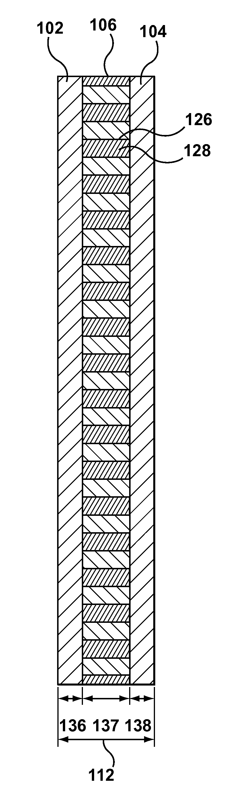
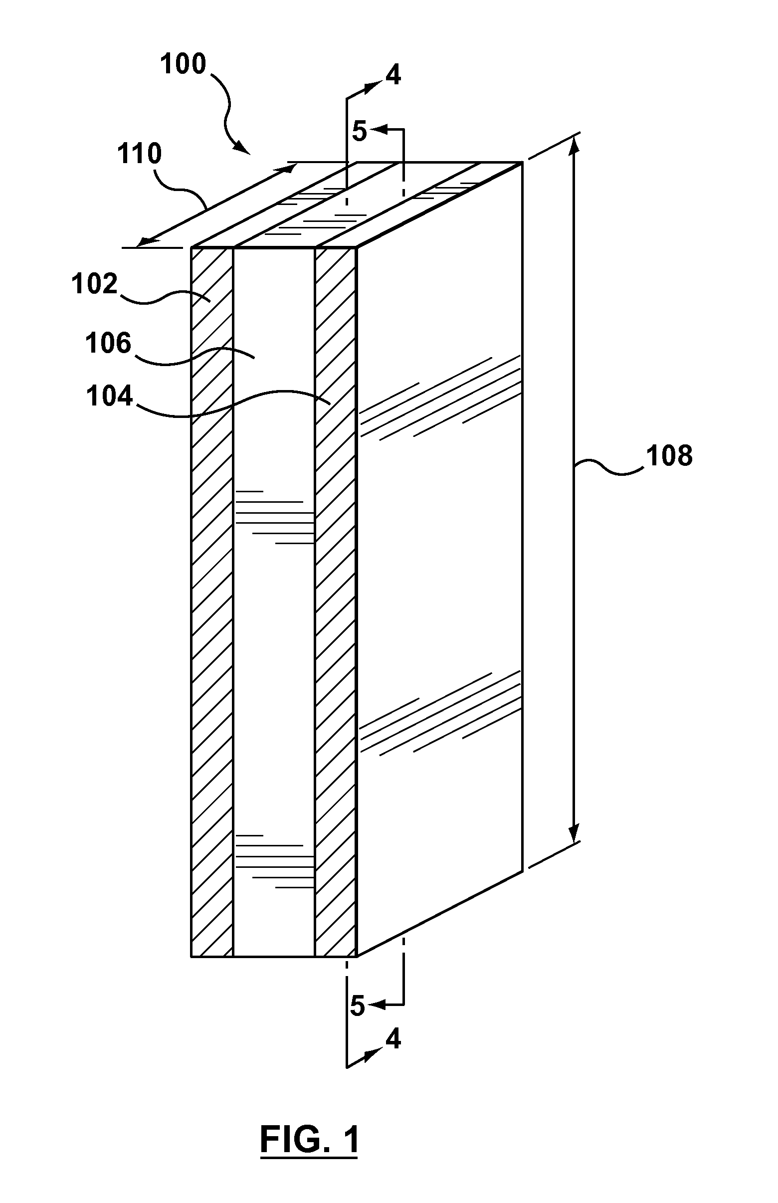
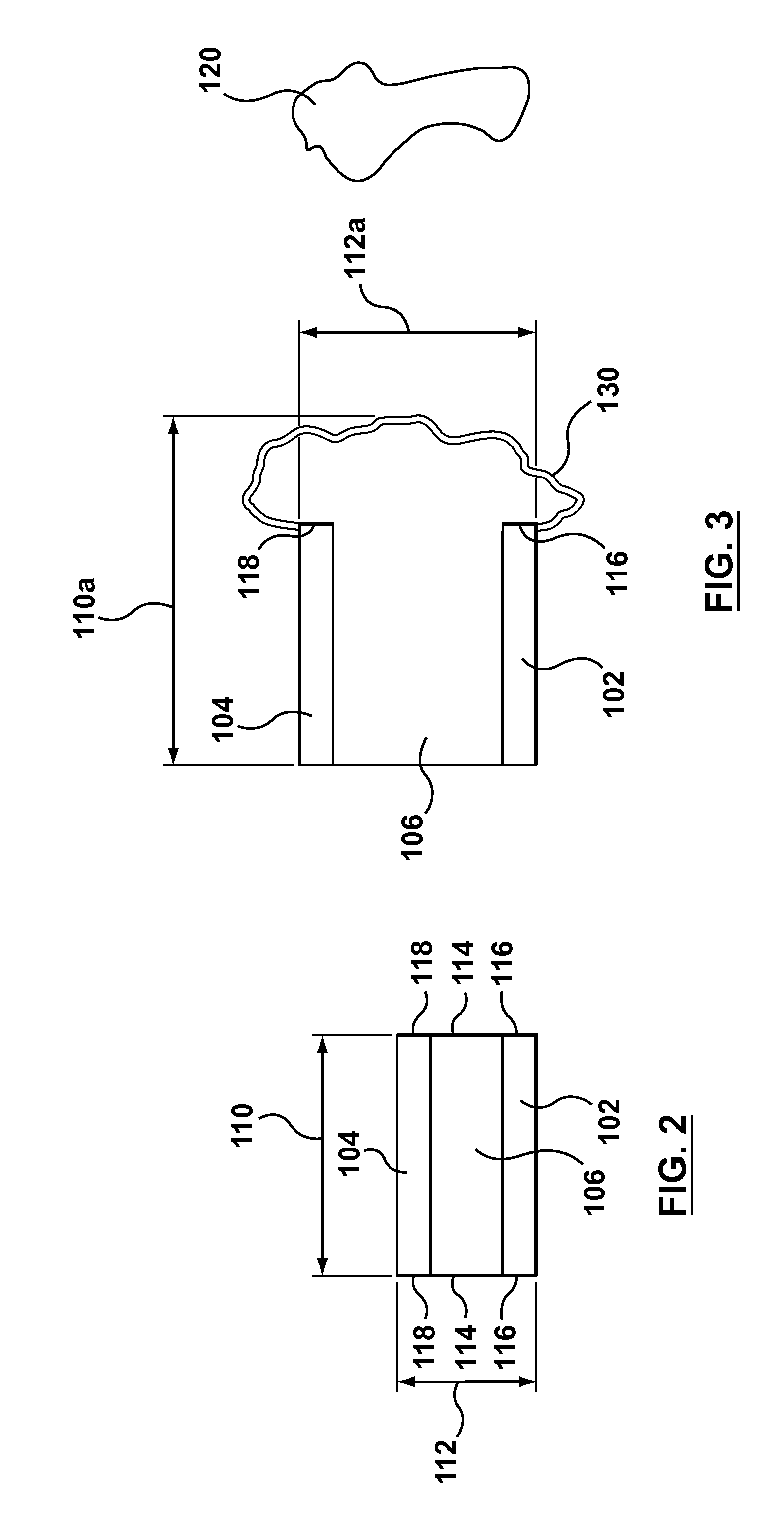
[0035]Referring to FIGS. 1-5, an intumescent strip 100 includes first and second layers 102, 104 of non-intumescent material bonded on opposing sides of a third layer 106 formed from an intumescent material. The intumescent strip 100 is configured to be attached to an edge of a fire door and has a length 108 and a width 110 that generally correspond to the dimensions of the portion of the fire door to be covered. The intumescent strip 100 is expandable from a non-expanded configuration (FIG. 2), to an expanded configuration (FIG. 3) when the strip 100 is exposed to high temperatures. The assembled strip 100 has variable strip thickness 112, which will be described in greater detail below.

[0036]The first and second layers 102, 104 are not intumescent and are formed from a thermoset sheet material, such as a high pressure phenolic laminate. Examples of high pressure phenolic laminates include paper-melamine laminates, Arborite® and Formica®.

[0037]The thickness 136, 138 of each layer c...


PUM

PropertyMeasurementUnit
temperaturesaaaaaaaaaa
melting temperatureaaaaaaaaaa

Abstract

An intumescent strip includes a first material layer and an opposing second material layer. A third material layer, formed from an intumescent material, is positioned between the first and second layers. The intumescent material includes a combination of intumescent particles suspended within a thermoplastic material. The intumescent particles have an activation temperature and are expandable when exposed to temperatures above the activation temperature. The thermoplastic material has a melting temperature that is lower than the activation temperature.

Description

CROSS-REFERENCE TO RELATED APPLICATION(S)[0001]This application claims the benefit of co-pending U.S. Provisional Application No. 61 / 358,458, filed Jun. 25, 2010, hereby incorporated by reference.FIELD[0002]This patent applies to the intumescent materials and components, and fire doors.INTRODUCTION[0003]Fire barriers are a passive means of fire protection. These include fire rated floors, walls, penetration barriers, and fire doors. The purpose of a fire barrier is to contain a fire within one compartment or room for a period of time.[0004]The testing method for fire doors in the United States has changed over the past 13 years from negative pressure to positive pressure. Under the UBC 7-2 1997 code requirements, swinging door assemblies are now required to be classified as tested under a positive pressure (UL10-C positive pressure fire test). The UL10-C positive pressure test more closely represents an actual fire in which a compartment containing a fire would be at a slightly elev...

Claims


Application Information

Patent Timeline
Patent Type & Authority Patents(United States)
IPC IPC(8): E04C2/00E06B1/04B32B7/08
CPCB32B3/266B32B7/08B32B7/12B32B27/06B32B27/20E06B5/161E06B5/164Y10T428/24331B32B2307/3065B32B2419/00E06B2003/7082B32B2264/108B32B2307/304B32B2307/50B32B2307/7242B32B2307/732Y10T428/31942Y10T428/249923
Inventor LANGILLE, KEVIN B.NGUYEN, DAT T.NGUYEN, HO T.BACH, AN CONG
Owner LANCOTEK PROD
Why Eureka
Try Eureka