Motor control apparatus and electric power steering apparatus

a technology of motor control and electric steering, which is applied in the direction of electric controllers, electronic commutators, dynamo-electric converter control, etc., can solve the problem of insufficient control accuracy, and achieve the effect of eliminating or suppressing a decrease in control accuracy and high accuracy

Active Publication Date: 2012-08-07
JTEKT CORP
View PDF16 Cites 7 Cited by
  • Summary
  • Abstract
  • Description
  • Claims
  • Application Information

AI Technical Summary

Benefits of technology

[0010]An aspect of the invention relates to a motor control apparatus that drives a motor with n phases (n is a natural number). The motor control apparatus includes a controller that determines a level of a command voltage used to drive the motor; a motor drive signal generator that generates a pulse width modulation (PWM) signal having a predetermined pulse width in each unit period, using a voltage whose level is equal to the level determined by the controller; and a motor drive circuit. The motor drive circuit has a plurality of switching elements that drive the motor based on the pulse width modulation signal from the motor drive signal generator, and a switching circuit that supplies a current into the motor when the pulse width modulation signal turns the plurality of switching elements on / off. The controller performs correction to correct the level of the command voltage to compensate for a change in a voltage applied to the motor drive circuit, according to on / off states of the switching elements. According to the aspect, the controller corrects the level of the command voltage to compensate for a change in the voltage applied to each phase due to a wiring resistance and the like. Therefore, it is possible to eliminate or suppress a decrease in control accuracy due to the wiring resistance and the like, and to drive the motor with high accuracy.

Problems solved by technology

Therefore, control accuracy may not be sufficiently high.

Method used


Image

  • Motor control apparatus and electric power steering apparatus
  • Motor control apparatus and electric power steering apparatus
  • Motor control apparatus and electric power steering apparatus

Examples


first embodiment

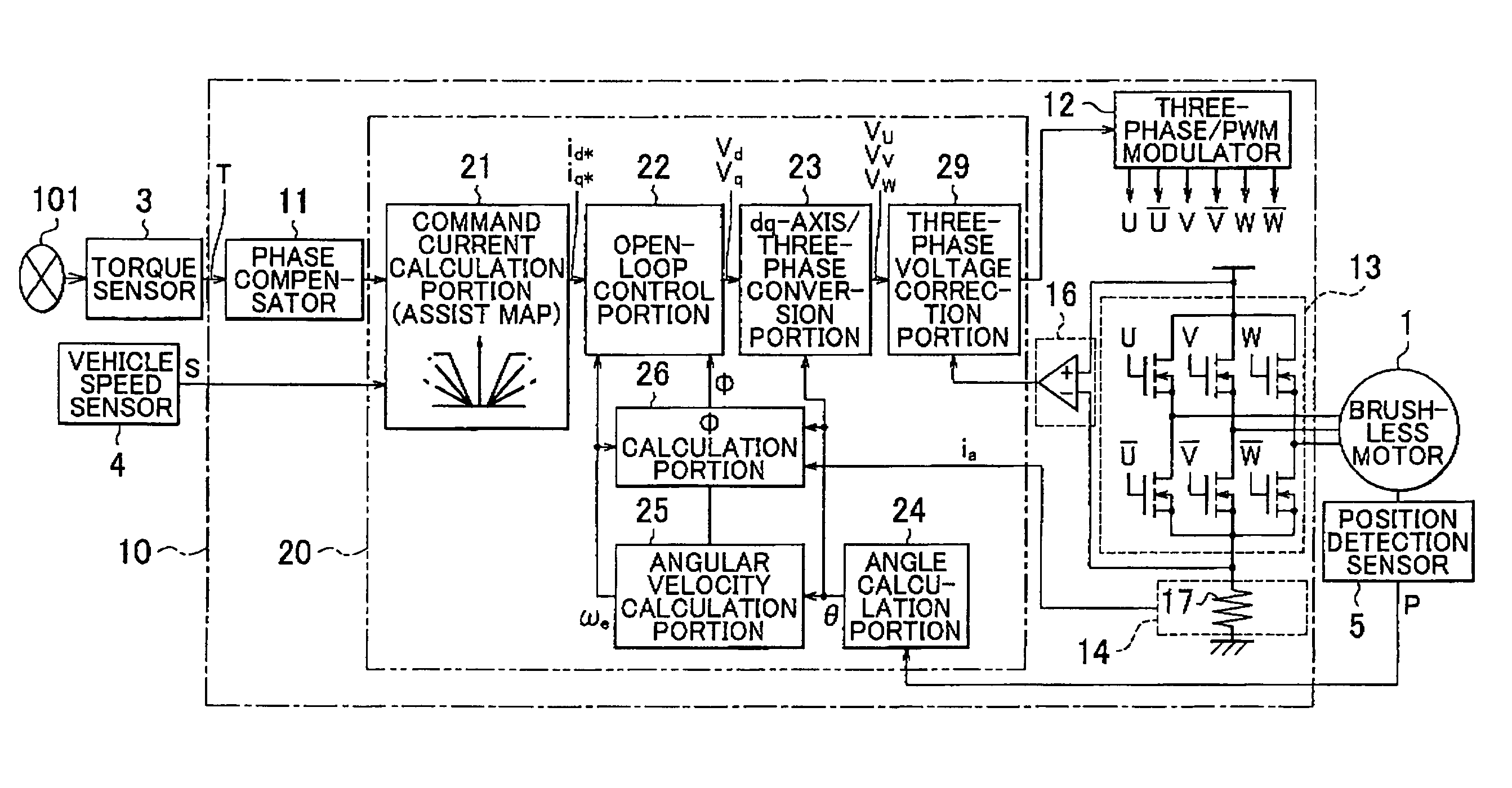
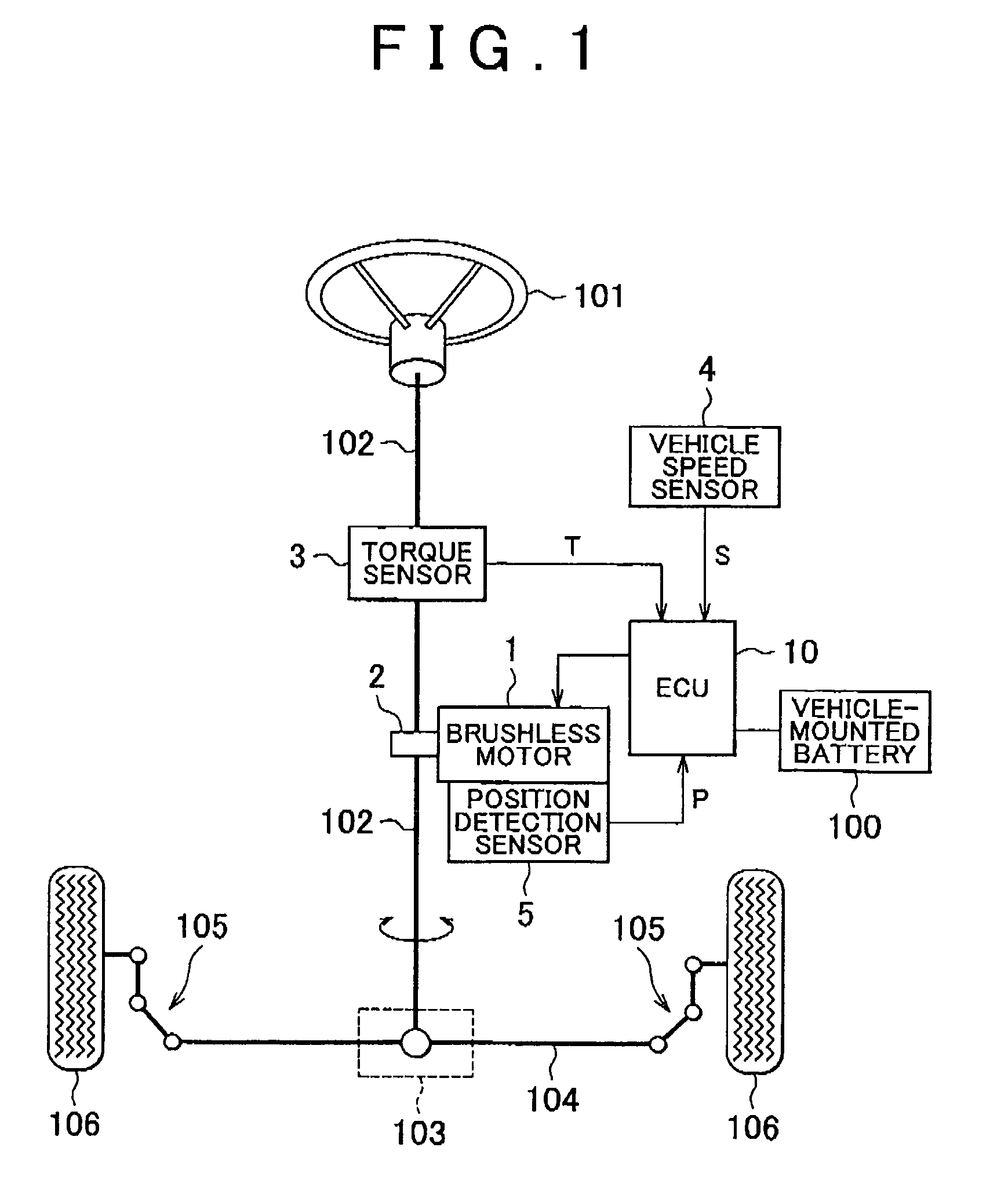
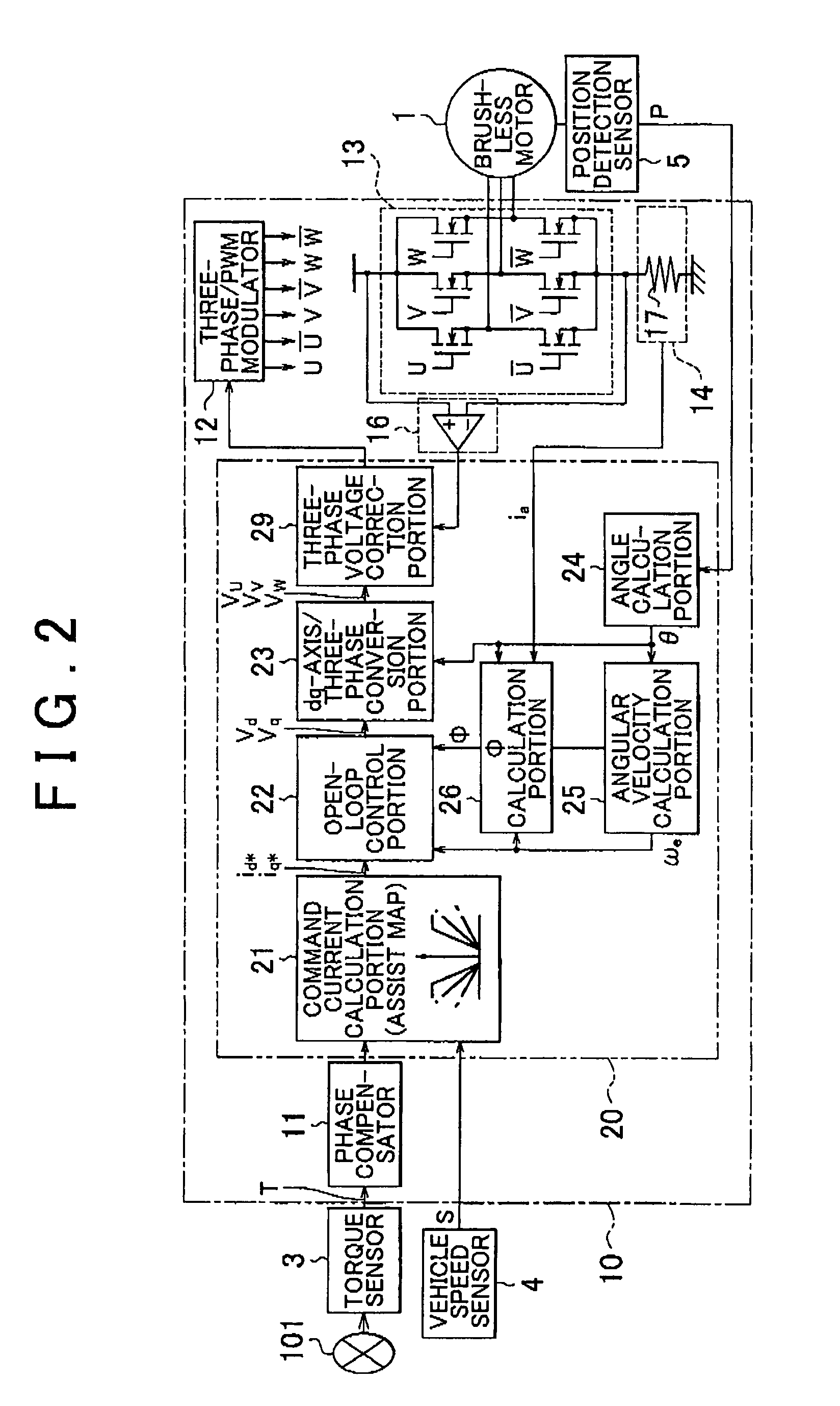
[0029]Hereinafter, each embodiment of the invention will be described with reference to the accompanying drawings. FIG. 1 is a schematic diagram showing the configuration of an electric power steering apparatus according to the invention, and the configuration of a vehicle relating to the electric power steering apparatus. The electric power steering apparatus shown in FIG. 1 is a column assist electric power steering apparatus that includes a brushless motor 1, a speed reducer 2, a torque sensor 3, a vehicle speed sensor 4, a position detection sensor 5, and an Electronic Control Unit (hereinafter, referred to as “ECU”) 10.

[0030]As shown in FIG. 1, a steering wheel 101 is fixed to one end of a steering shaft 102. A rack shaft 104 is coupled to the other end of the steering shaft 102 through a rack pinion mechanism 103. Both ends of the rack shaft 104 are coupled to respective wheels 106 through a coupling member 105 that includes a tie rod and a knuckle arm. When a driver rotates t...

second embodiment

[0075]FIG. 8 is a flowchart showing the procedure of a control executed by the three-phase voltage correction portion 39 to perform correction in the In step S20 shown in FIG. 8, the three-phase voltage correction portion 39 acquires the voltage Vb at the both ends of the motor drive circuit 13 detected by the voltage sensor 16 during the period from the time point t1 to the time point t2 in FIG. 4, the decreased voltage Vb1 at the both ends of the circuit detected during the period from the time point t2 to the time point t3, and the further decreased voltage Vb2 at the both ends of the circuit detected during the period from the time point t3 to the time point t5. The acquisition of the voltage Vb1 or the acquisition of the voltage Vb2 may be omitted, as described later.

[0076]Next, in step S22, the three-phase voltage correction portion 39 acquires the u-phase current iu among the drive currents of three phases during the period from the time point t2 to the time point t3 in FIG....

third embodiment

[0089]FIG. 9 is a flowchart showing the procedure of a control executed by the three-phase voltage correction portion 39 to perform the correction in the The processes in steps S20 to S24, S26, and S28 (the operation performed by the three-phase voltage correction portion 39) shown in FIG. 9 are the same as the processes in steps S20 to S24, S26, and S28 shown in FIG. 8, and therefore, the description thereof will be omitted.

[0090]As evident from comparison between the processes in steps shown in FIG. 9 and the processes in steps shown in FIG. 8, in the third embodiment, the process of calculating the limit value in step S25 is added to the processes in the second embodiment, and the process in step S25 is executed at an appropriate timing. More specifically, after the process in step S25 (described in detail later) is executed, the three-phase voltage correction portion 39 calculates the correction period ΔT1 and corrects the v-phase command voltage Vv, and calculates the correcti...


PUM


Abstract

An angle calculation portion of a motor control apparatus determines an angle θ of a rotor, and an angular velocity calculation portion determines an angular velocity ωe of the rotor. A command current calculation portion determines command currents id* and iq* on dq axes, based on a steering torque T and a vehicle speed S. An open-loop control portion determines command voltages vd and vq on the dq axes based on the command currents id* and iq* and the angular velocity ωe, according to circuit equations of a motor. A dq-axis / three-phase conversion portion converts the command voltages vd and vq to command voltages of three phases. A three-phase voltage correction portion corrects the command voltage so that an actual time average value of a voltage applied to each phase is equal to a time average value of a voltage that is to be applied to the phase if the voltage is not decreased, in order to compensate for a decrease in the applied voltage. By performing the correction, it is possible to eliminate or suppress a decrease in control accuracy due to a wiring resistance and the like.

Description

INCORPORATION BY REFERENCE[0001]The disclosure of Japanese Patent Applications No. 2008-214978 and No. 2008-325594 respectively filed on Aug. 25, 2008 and Dec. 22, 2008, each including the specification, drawings and abstract, are incorporated herein by reference in their entireties.BACKGROUND OF THE INVENTION[0002]1. Field of the Invention[0003]The invention relates to a motor control apparatus, and an electric power steering apparatus including the motor control apparatus.[0004]2. Description of the Related Art[0005]An electric power steering apparatus that provides a steering assist force to a steering mechanism of a vehicle by driving an electric motor in accordance with a steering torque applied to a steering wheel by a driver has been used. A brush motor has been widely used as the electric motor of the electric power steering apparatus. Recently, a brushless motor has also been used as the electric motor of the electric power steering apparatus, from the viewpoints of improve...

Claims


Application Information

Patent Timeline
Patent Type & Authority Patents(United States)
IPC IPC(8): G05B11/28B62D5/02B62D5/04B62D6/00H02P6/06H02P6/08H02P6/17
CPCB62D5/046H02P21/145H02P27/08H02P2205/05H02P21/16
Inventor UEDA, TAKESHINAGASE, SHIGEKI
Owner JTEKT CORP
Why Eureka
Try Eureka