Motor control apparatus and electric power steering apparatus
a technology of motor control and electric steering, which is applied in the direction of electric generator control, dynamo-electric converter control, dynamo-electric gear control, etc., can solve the problem of insufficient control accuracy, and achieve the effect of eliminating or suppressing a decrease in control accuracy and high accuracy
- Summary
- Abstract
- Description
- Claims
- Application Information
AI Technical Summary
Benefits of technology
Problems solved by technology
Method used
Image
Examples
first embodiment
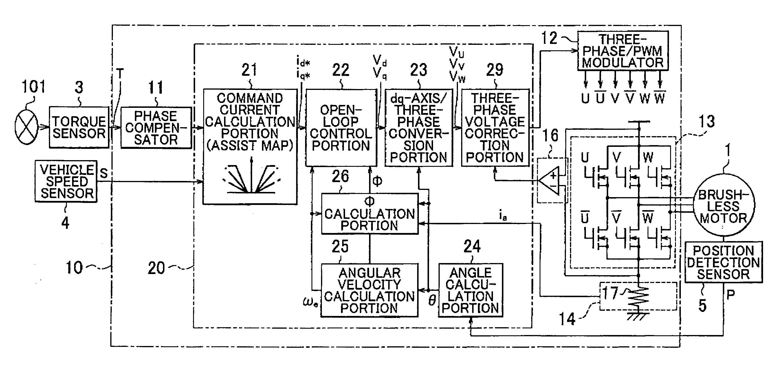
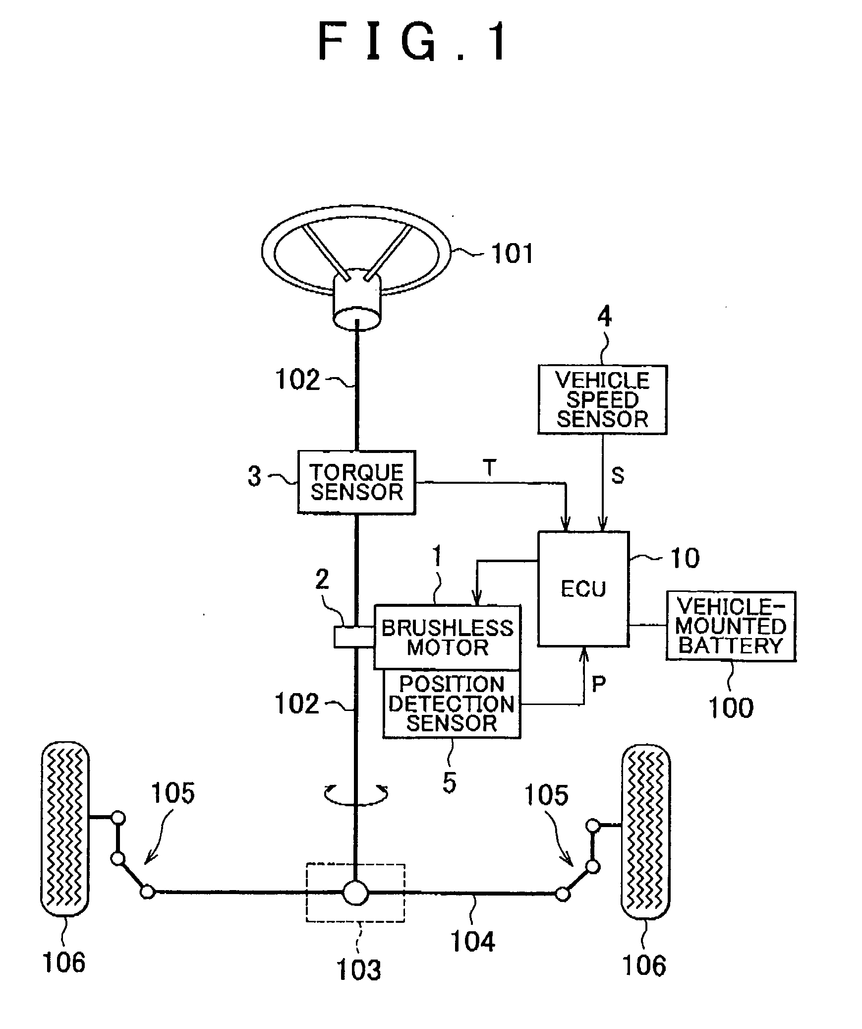
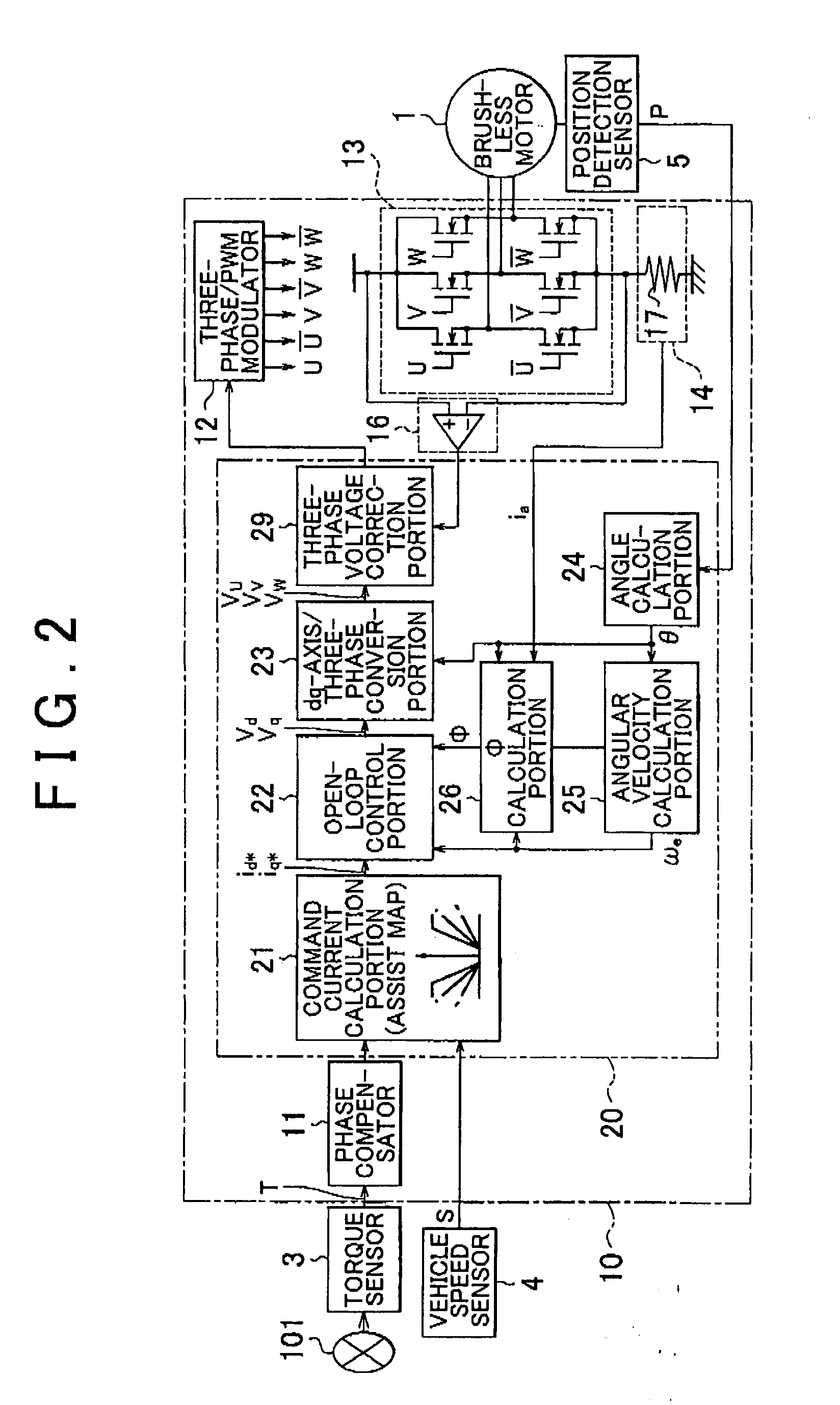
[0029]Hereinafter, each embodiment of the invention will be described with reference to the accompanying drawings. FIG. 1 is a schematic diagram showing the configuration of an electric power steering apparatus according to the invention, and the configuration of a vehicle relating to the electric power steering apparatus. The electric power steering apparatus shown in FIG. 1 is a column assist electric power steering apparatus that includes a brushless motor 1, a speed reducer 2, a torque sensor 3, a vehicle speed sensor 4, a position detection sensor 5, and an Electronic Control Unit (hereinafter, referred to as “ECU”) 10.
[0030]As shown in FIG. 1, a steering wheel 101 is fixed to one end of a steering shaft 102. A rack shaft 104 is coupled to the other end of the steering shaft 102 through a rack pinion mechanism 103. Both ends of the rack shaft 104 are coupled to respective wheels 106 through a coupling member 105 that includes a tie rod and a knuckle arm. When a driver rotates t...
second embodiment
[0075]FIG. 8 is a flowchart showing the procedure of a control executed by the three-phase voltage correction portion 39 to perform correction in the In step S20 shown in FIG. 8, the three-phase voltage correction portion 39 acquires the voltage Vb at the both ends of the motor drive circuit 13 detected by the voltage sensor 16 during the period from the time point t1 to the time point t2 in FIG. 4, the decreased voltage Vb1 at the both ends of the circuit detected during the period from the time point t2 to the time point t3, and the further decreased voltage Vb2 at the both ends of the circuit detected during the period from the time point t3 to the time point t5. The acquisition of the voltage Vb1 or the acquisition of the voltage Vb2 may be omitted, as described later.
[0076]Next, in step S22, the three-phase voltage correction portion 39 acquires the u-phase current iu among the drive currents of three phases during the period from the time point t2 to the time point t3 in FIG....
third embodiment
[0089]FIG. 9 is a flowchart showing the procedure of a control executed by the three-phase voltage correction portion 39 to perform the correction in the The processes in steps S20 to S24, S26, and S28 (the operation performed by the three-phase voltage correction portion 39) shown in FIG. 9 are the same as the processes in steps S20 to S24, S26, and S28 shown in FIG. 8, and therefore, the description thereof will be omitted.
[0090]As evident from comparison between the processes in steps shown in FIG. 9 and the processes in steps shown in FIG. 8, in the third embodiment, the process of calculating the limit value in step S25 is added to the processes in the second embodiment, and the process in step S25 is executed at an appropriate timing. More specifically, after the process in step S25 (described in detail later) is executed, the three-phase voltage correction portion 39 calculates the correction period ΔT1 and corrects the v-phase command voltage Vv, and calculates the correcti...
PUM
 Abstract
Description
Claims
Application Information
 - R&D
- Intellectual Property
- Life Sciences
- Materials
- Tech Scout
- Unparalleled Data Quality
- Higher Quality Content
- 60% Fewer Hallucinations
Browse by: Latest US Patents, China's latest patents, Technical Efficacy Thesaurus, Application Domain, Technology Topic, Popular Technical Reports.
© 2025 PatSnap. All rights reserved.Legal|Privacy policy|Modern Slavery Act Transparency Statement|Sitemap|About US| Contact US: help@patsnap.com


