Power system

a power transfer system and wireless technology, applied in the direction of dynamo-electric converter control, ac network to reduce harmonics/ripples, instruments, etc., can solve the problems of requiring rectifiers in portable devices, unwanted interference, exacerbate the situation, etc., and achieve the effect of reducing the spurious tones generated by such a driver circuit and avoiding interferen

Active Publication Date: 2012-08-07
BEIJING XIAOMI MOBILE SOFTWARE CO LTD
View PDF13 Cites 42 Cited by
  • Summary
  • Abstract
  • Description
  • Claims
  • Application Information

AI Technical Summary

Benefits of technology

[0013]means for adapting the compensation signal to minimise the power at frequencies other than the first frequency at the power detector.
[0078]This aspect has the advantage that an inexpensive and efficient driver circuit can be used and the spurious tones generated by such a driver circuit can be reduced.

Problems solved by technology

In a wireless charger, it is inevitable that any frequency components present on the primary coil will be radiated into the atmosphere, because it is not possible to adequately shield the coil and still permit coupling to a portable device.
However the primary inductor can act as a very efficient antenna at higher harmonics and this can cause unwanted interference.
A further issue which can exacerbate the situation is that a rectifier is required in the portable device.

Method used


Image

  • Power system
  • Power system
  • Power system

Examples


sixth embodiment

[0099]FIG. 11 shows what is known as the invention, which is a system for reducing the magnitude of the distortion components present in the primary coil 20. An inverter 18 is used to drive a primary coil 20 with a rectangular signal. The signal may be a square-wave signal or it may be a pulse-width modulated signal in which the duty cycle is varied to vary the amplitude of the signal applied to the primary coil. The inverter 18 is driven by a reference oscillator 30 at frequency f1.

[0100]In series with the primary coil 20 is a capacitor 26 such that the combination is resonant at f1 when the secondary load is present. Also in series with the coil 20 is a sense transformer 32 and an injection transformer 34.

[0101]The sense transformer 32 typically has one turn on the primary coil side and 20 to 50 turns on the other side in order to present minimal impedance in the primary coil circuit. The sense transformer 32 is used to measure the harmonic distortion present on the primary coil 2...

first embodiment

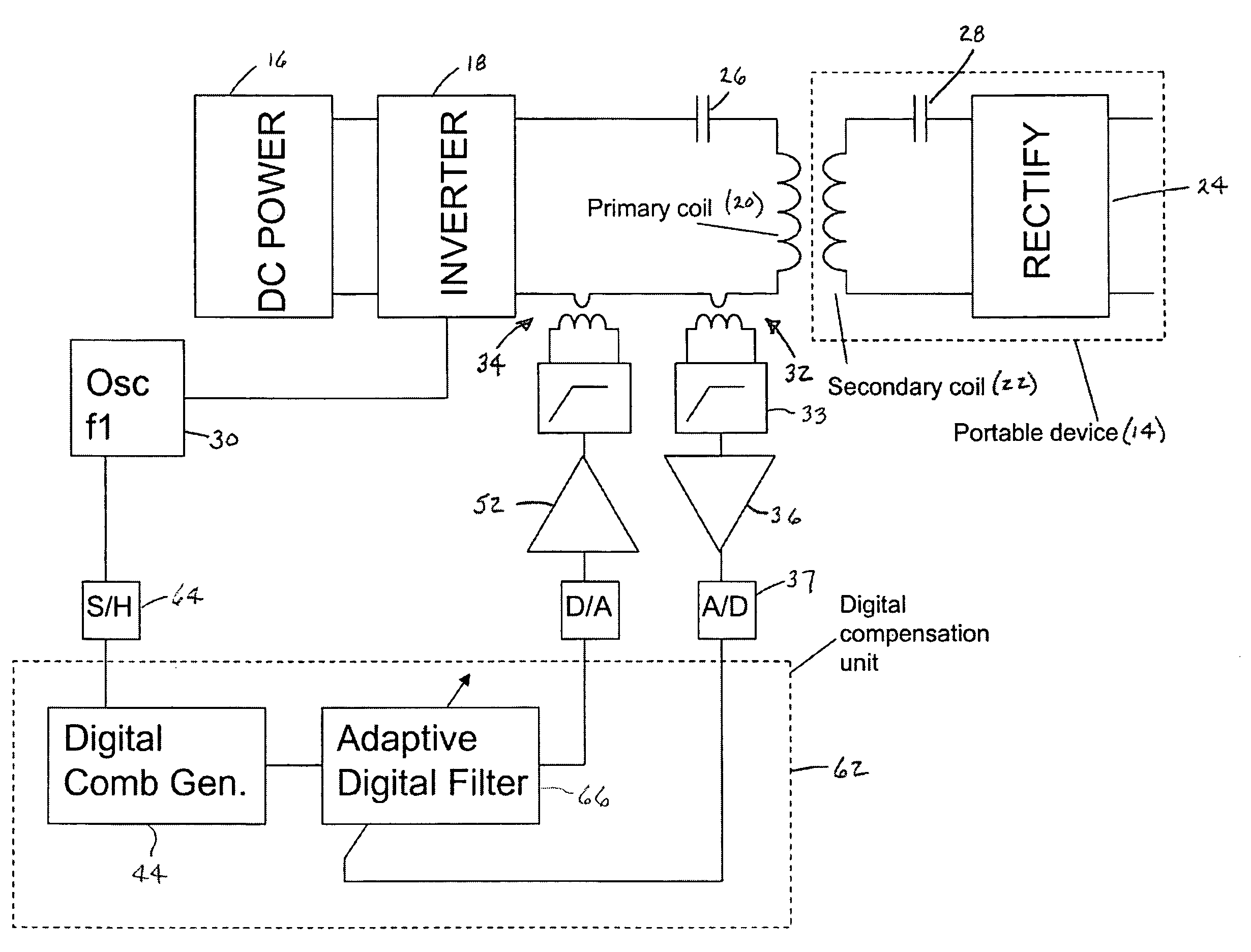
[0109]FIG. 6 shows what is known as the invention—and currently the preferred embodiment—in which the compensation is performed digitally. In this system the main primary and secondary circuits are the same as previously described, and they use the same sense and injection transformers. However, in this arrangement, the compensation signal is generated digitally. A digital compensation circuit (DCC) or unit 62 is used, which is clocked at a higher frequency than f1. For instance, f1 may be at 100 kHz; and the clock frequency of the digital compensation circuit may be 100 MHz. This may be implemented as an ASIC, an FPGA, a microprocessor, or a digital signal processor (DSP). Typically this device can process numbers using fixed point arithmetic, though floating point devices are also available. The DCC 62 takes the reference oscillator 30 as an input. This is sampled with a sample and hold amplifier 64 and used to generate the discrete tones digitally. There are many algorithms for g...

second embodiment

[0112]FIG. 7 what is known as the invention. This embodiment is a digital implementation of the FIG. 6 embodiment. Instead of using a tapped delay line filter, each harmonic is sensed individually. If the system is linear, then each harmonic can be adjusted individually. It should therefore be simpler to adjust the system to nullify each harmonic. The FIG. 7 embodiment works well when the system is linear. The FIG. 6 embodiment likely works better when the system is nonlinear because the harmonics are interrelated.


PUM


Abstract

The specification discloses a wireless power charging system in which undesired frequencies in the primary coil are cancelled. Exemplary undesired frequencies are the harmonics of the primary coil drive signal. The system includes a sense transformer / coil, an injection transformer / coil, and a compensation signal generator. The sense transformer / coil senses the signal in the primary coil. The compensation signal generator receives the sensed signal and generates an injection signal whose constituent parts are equal in amplitude to, but pi phase different from, each undesired frequency. The combined signal is injected into the primary through the injection transformer / coil so that the injection signal cancels the undesired frequencies in the primary coil.

Description

BACKGROUND OF THE INVENTION[0001]The present invention relates to wireless power transfer systems, and more particularly to such systems incorporating circuitry and / or methodologies for attenuating or cancelling undesirable spurious signals, such as harmonics.[0002]A wireless power transfer system 10 for transferring power from a charger 12 to a portable device 14 is shown in FIG. 1. There is a DC power source 16 in the charger 12 which is converted to an alternating current using an inverter 18. Typically a half-bridge circuit is used to generate a rectangular signal of either high voltage and / or high current. This signal is applied to a primary inductive coil 20. Within the portable device 14 there is a secondary coil 22 which is electromagnetically coupled to the primary coil 20 when the device is appropriately positioned on the charger 12. An alternating voltage is induced within the secondary coil 22. This voltage may be rectified using a diode bridge 24 to provide a DC voltage...

Claims


Application Information

Patent Timeline
Patent Type & Authority Patents(United States)
IPC IPC(8): H02M1/12H02J3/01
CPCH02J7/025H02M1/12H02M7/48H02M2001/0012H02M2007/4815Y02B70/1441H02J50/80H02J7/00034Y02B70/10H02M1/0012H02M7/4815H02J50/70H02J50/12
Inventor FELLS, JULIAN ANDREW JOHN
Owner BEIJING XIAOMI MOBILE SOFTWARE CO LTD
Why Eureka
Try Eureka