
Laser capture microdissection system and electric moving stage thereof

a microdissection system and laser technology, applied in the field of electric moving stage thereof, can solve the problems of contaminating the target cell, affecting so as to achieve the effect of significantly improving the overall speed and performance of the laser capture microdissection system

Inactive Publication Date: 2012-08-21
CHIEN MING CHEN +1
View PDF6 Cites 2 Cited by
  • Summary
  • Abstract
  • Description
  • Claims
  • Application Information

AI Technical Summary

Benefits of technology

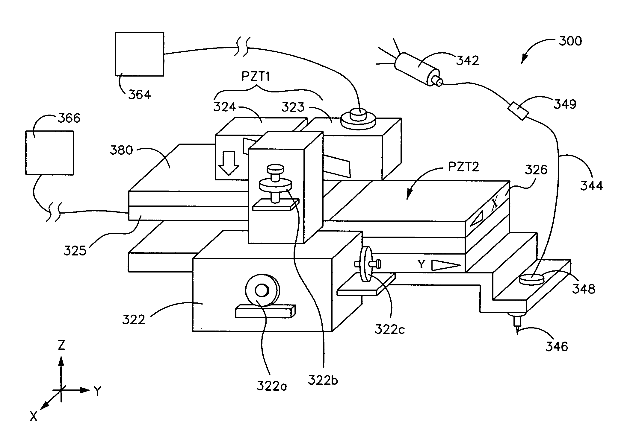
[0011]Accordingly, the object of the invention is to provide an electric moving stage for a laser capture microdissection system. After capturing the target object via the image observed by the charge coupled device (CCD) camera, the operation and the control of the man-machine interface is accomplished effectively to promote the overall speed of the laser capture microdissection (LCM) system.
[0022]The movement of the stage unit and the movement of the fiber probe in the present invention are separated and independent of each other. The movement of the fiber probe is shifted in three-dimensional (X, Y and Z axis) direction. Whereas, the movement of the stage unit is relatively confined in planar two-dimensional (X and Y axis) direction. The overall speed and performance of the LCM system is enable be significantly improved via the man-machine interface.

Problems solved by technology

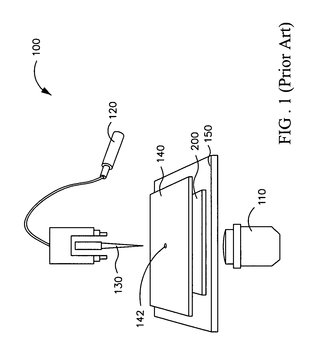
When the diameter of the target cell is smaller than 5 micrometer, the captured parts of cell inevitably contain the tissue close to the target cell, probably contaminating the target cell.
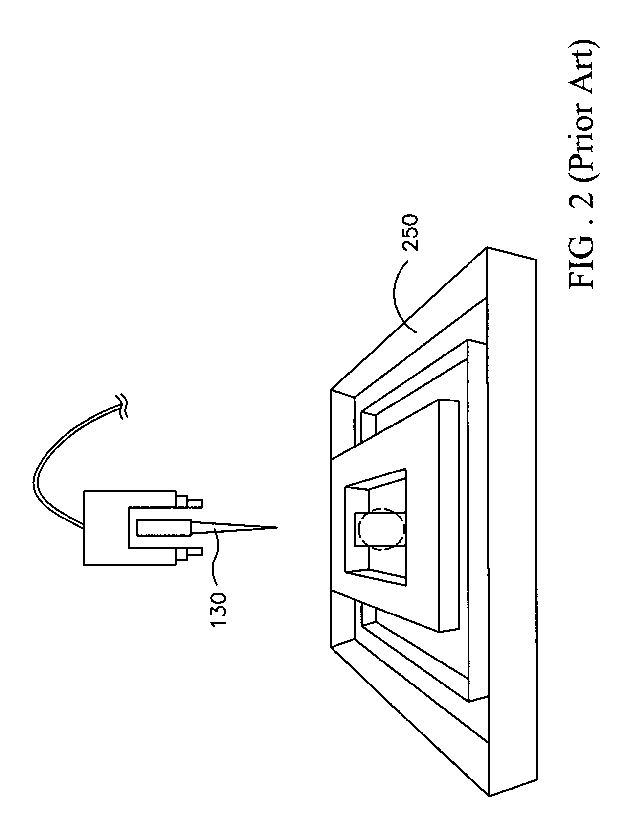
However, because of no fine tuning feature for precise movement of the conventional stage 250, the alignment of the fiber probe 130 with the target cells is a very difficult and hours time-consuming task so that the overall microdissection process becomes very slow.

Method used


Image

  • Laser capture microdissection system and electric moving stage thereof
  • Laser capture microdissection system and electric moving stage thereof
  • Laser capture microdissection system and electric moving stage thereof

Examples


Embodiment Construction

[0033]In the following detailed description of the preferred embodiments, reference is made to the accompanying drawings which form a part hereof, and in which is shown by way of illustration specific embodiments in which the invention may be practiced. In this regard, directional terminology, such as “top,”“bottom,”“front,”“back,” etc., is used with reference to the orientation of the Figure(s) being described. The components of the present invention can be positioned in a number of different orientations. As such, the directional terminology is used for purposes of illustration and is in no way limiting. On the other hand, the drawings are only schematic and the sizes of components may be exaggerated for clarity. It is to be understood that other embodiments may be utilized and structural changes may be made without departing from the scope of the present invention. Also, it is to be understood that the phraseology and terminology used herein are for the purpose of description and...


PUM

PropertyMeasurementUnit
distanceaaaaaaaaaa
thicknessaaaaaaaaaa
triggered timeaaaaaaaaaa

Abstract

A laser capture microdissection system includes a laser illuminator, a fiber and an electric moving stage. The fiber has a probe terminal and a coupling terminal for being coupled to the laser illuminator. The electric moving stage includes a fiber probe holder, a driving mechanism for vertical shift, a stage unit, a driving mechanism for horizontal shift and an electronic control unit. The driving mechanism for vertical shift serves for driving the fiber probe holder to shift in microscale. The stage unit has a nanoscale shift controller, a placing portion, wherein the nano-scale shift controller is connected to the placing portion, and the placing portion is located under the fiber probe holder. The driving mechanism for horizontal shift serves for driving the stage unit to shift in microscale. The electronic control unit is electrically connected to the nanoscale shift controller and the driving mechanism for horizontal shift.

Description

BACKGROUND OF THE INVENTION[0001](1) Field of the Invention[0002]The invention relates to a laser capture microdissection system and an electric moving stage thereof, especially relates a laser capture microdissection system and an electric moving stage thereof for serving to capture the nanoscale particles or biological samples, such as the nanoscale tissue cell.[0003](2) Description of the Prior Art[0004]Following the advancement and accumulation of the optoelectronics knowledge as well as the progress in the optoelectronics technology, engineers and scientists are urged to exploit and employ the laser technology together with precise electric position control into nanoscale so that an user-friendly simple opto-electric positioning mechanism can be worked out for capture, separation or dissection of the target cell specimen via laser technology in simple, quick and precise manner.[0005]Currently, laser systems for capture, separation or dissection of the target cell specimen can b...

Claims


Application Information

Patent Timeline
Patent Type & Authority Patents(United States)
IPC IPC(8): G01N1/00
CPCG01N1/2813G01N2001/284
Inventor CHEN, CHIEN-MINGLEE, JEN-AI
Owner CHIEN MING CHEN
Learn More