Subsurface upflow wetland system for nutrient and pathogen removal in wastewater treatment systems

a wastewater treatment system and subsurface technology, applied in biological water/sewage treatment, water cleaning, multi-stage water/sewage treatment, etc., can solve the problems of reducing the service life of the system, and increasing the maintenance burden of the system, so as to reduce the burden of maintenance and improve the service life , the effect of reducing the cos

Active Publication Date: 2012-08-28
UNIV OF CENT FLORIDA RES FOUND INC
View PDF8 Cites 128 Cited by
  • Summary
  • Abstract
  • Description
  • Claims
  • Application Information

AI Technical Summary

Benefits of technology

[0045]A seventh objective of the invention is to provide methods, systems and sorption media for lower maintenance burden, lower cost, higher benefit cost ratio, highly sustainable with material recycling and reuse, highly flexible with any landscape and built environment, highly applicable in dealing with drought impact or other emergency events when various sources of wastewater and stormwater can be polished for reuse, highly compatible with any type of Low Impact Development (LID) technologies in dealing with stormwater management, highly compatible with any type of architecture landscape design as an integral part of the green building program.

Problems solved by technology

Due to environmental health concern, the conventional centralized sewage collection, treatment, and disposal systems are no longer able to fully cater to the needs of treating on-site wastewater effluent which represent a large fraction of nutrient loads and pathogen impacts.
Although properly managed on-site wastewater treatment and disposal system offers several advantages over centralized wastewater treatment facilities, conventional onsite system installations might not be adequate for minimizing nitrate contamination of groundwater, removing nutrient compounds, and attenuating pathogenic organisms.
However, systems may create a higher, undesirable level of nutrient loading if improperly designed or managed (Hoover, 2002).
As the nutrient impact on groundwater quality becomes a big concern, conventional on-site wastewater treatments are no longer able to fully conform to the gradually tougher water quality standards.
The current major concern of on-site wastewater treatment is that a large fraction of nutrient loads, such as nitrogen and phosphorus, flow into the aquatic system and adversely affect the water quality and public health.
Elevated nutrient and pathogen levels in groundwater may cause health problems in children and may impair or destroy environmentally sensitive habitat.
Increased nutrient and pathogen concentrations in surface waters may also lead to excess plant and algal growth and water pollution.
When plants and algae die and decay, it results in lower dissolved oxygen levels and overall water quality.
The main disadvantages associated with aerobic treatment units are the need for external power source and higher maintenance level required to ensure proper system operation.
However, owners need to periodically rake and replace clogged surface sand. regardless of the disadvantages of each of these two on-site wastewater treatment alternatives mentioned above, it can be seen that denitrification in these two alternatives does not come up to expectations due to the presence of aerobic environment.
This kind of model oversimplified the constructed wetland treatment system, which has an extremely complicated physical, chemical and biological process.
However, the fatal limitation of the first-order kinetics is that the constructed wetland system is required to keep the same flow rate, concentration and ideal plug flow.
The models mentioned above just provide a limited understanding of specific items, which were even separately analyzed.
When researchers revel in improving CWs, the complexity of the latest generation model insensibly deters the public prevalence of the CW model application.
The limited useful results from real practice further retard the calibration and optimization of the theoretical modeling work.

Method used


Image

  • Subsurface upflow wetland system for nutrient and pathogen removal in wastewater treatment systems
  • Subsurface upflow wetland system for nutrient and pathogen removal in wastewater treatment systems
  • Subsurface upflow wetland system for nutrient and pathogen removal in wastewater treatment systems

Examples


Embodiment Construction

[0071]Before explaining the disclosed embodiments of the present invention in detail it is to be understood that the invention is not limited in its application to the details of the particular arrangements shown since the invention is capable of other embodiments. Also, the terminology used herein is for the purpose of description and not of limitation.

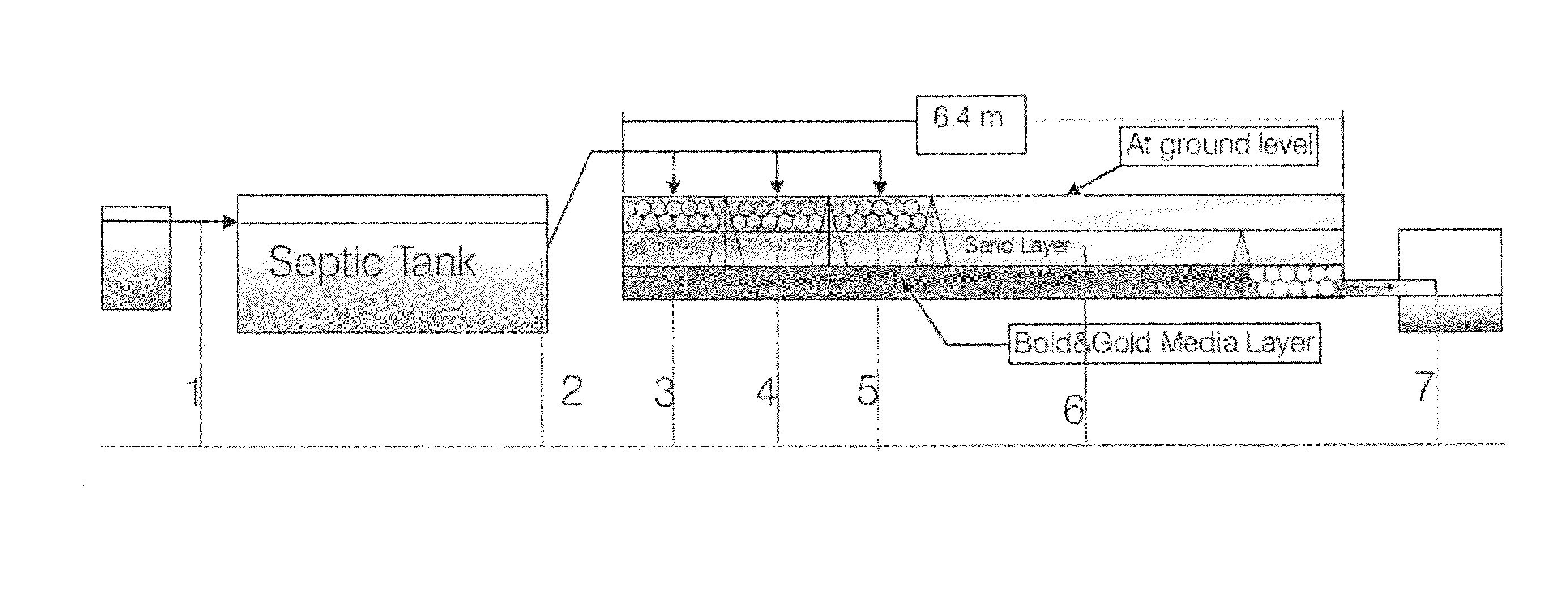
[0072]The following is a list of reference numerals used in the description and the drawings to identify components:[0073]100 subsurface upflow wetland[0074]110 inlet pipe[0075]115 outlet pipe[0076]120 gravel layer[0077]130 sand layer[0078]140 pollution control medium layer[0079]150 plant growth medium layer[0080]160 sampling ports[0081]170 plants[0082]180 air inlet port

[0083]A subsurface upflow wetland (SUW) system receives septic tank effluent and was tested up to 454 m3 (120 gallon) per day with each of the four SUW cells treating 30 gallons per day in our study. The septic tank before the SUWs has a size of 1000 gallon per day pr...


PUM

PropertyMeasurementUnit
temperatureaaaaaaaaaa
hydraulic retention timeaaaaaaaaaa

Abstract

Methods and systems for a subsurface upflow wetland for wastewater treatment that includes a series of parallel treatment cells, each cell including from bottom to top, a layer of gravel, a layer of sand over the gravel to remove pathogens from a septic effluent, a pollution control medium above the sand layer to remove nutrients, total suspended solid, and biochemical oxygen demand and a growth media mixture layered on top of the pollution control media to grow plants, and a gravity distribution system to distribute effluent to the series of parallel treatment cells. The pollution control medium includes at least one recycled material and at least one naturally occurring material. In an embodiment it includes recycled tire crumb, sand and limestone or recycled tire crumb, compost, sand and limestone.

Description

[0001]This invention is a continuation-in-part of U.S. application Ser. No. 13 / 011,341 filed on Jan. 21, 2011, now U.S. Pat. No. 8,101,079, which is a divisional application of U.S. application Ser. No. 12 / 208,617 filed on Sep. 11, 2008, now U.S. Pat. No. 7,927,484, and claims the benefit of priority to U.S. Provisional Application No. 61 / 327,403 filed on Apr. 23, 2010.FIELD OF THE INVENTION[0002]This invention relates to wastewater treatment and, in particular, to methods, systems and sorption media for combined sewer overflow and on-site wastewater treatment using a subsurface upflow wetland system for septic wastewater effluent treatment.BACKGROUND AND PRIOR ART[0003]Due to environmental health concern, the conventional centralized sewage collection, treatment, and disposal systems are no longer able to fully cater to the needs of treating on-site wastewater effluent which represent a large fraction of nutrient loads and pathogen impacts. They include not only nitrogen (N) and ph...

Claims


Application Information

Patent Timeline
Patent Type & Authority Patents(United States)
IPC IPC(8): C02F3/32C02F3/30
CPCB01J20/10B01J20/12B01J20/16B01J20/24B09C1/002C02F3/046C02F3/327B01J2220/46B01J2220/4825B01J2220/4831B01J2220/4893C02F1/281C02F1/286C02F3/302C02F3/308C02F2103/005C02F2103/06Y02W10/10
Inventor CHANG, NI-BINWANIELISTA, MARTIN P.
Owner UNIV OF CENT FLORIDA RES FOUND INC
Why Eureka
Try Eureka