
Method for checking and rotating electronic components

a technology of electronic components and rotating parts, applied in the direction of electrical equipment, pile separation, instruments, etc., can solve the problems of reducing the throughput of the device and increasing the operating cost, and achieve the effect of saving time and cos

Active Publication Date: 2012-09-04
MUEHLBAUEHR AG
View PDF17 Cites 3 Cited by
  • Summary
  • Abstract
  • Description
  • Claims
  • Application Information

AI Technical Summary

Benefits of technology

The present invention provides a device and method for checking and rotating electronic component parts, particularly flip chips, with a pivoting part for rotating the components. The device is cost-effective and time-saving. The device includes a part with a pivoting point for rotating the components, with two pickup elements for holding and rotating the components. The part has a through opening for facing the substrate during rotation. The device allows for efficient and quick inspection and pickup of components, resulting in increased throughput and reduced operating costs. The design of the pivoting part allows for optimal attachment of vacuum pipettes and a simple manufacturing process. A camera is also included for checking the position of the previously rotated and deposited chip. The device uses a predefinetable time delay to avoid blurred images caused by the rotating part.

Problems solved by technology

Such a sequence of successive steps leads to a high time requirement for the overall process of checking and rotating a chip, and thereby reduces the throughput of the device.
It therefore also results in higher operating costs.

Method used


Image

  • Method for checking and rotating electronic components
  • Method for checking and rotating electronic components
  • Method for checking and rotating electronic components

Examples


Embodiment Construction

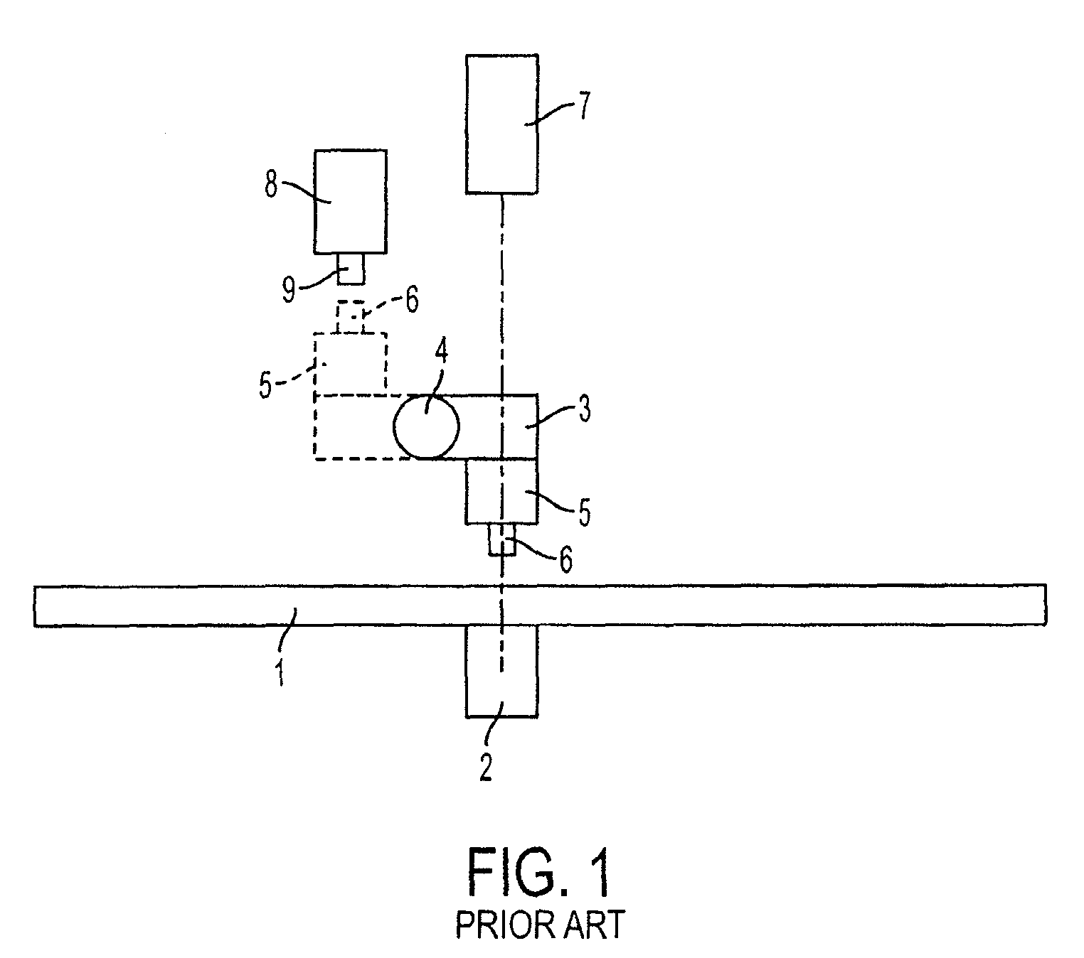
[0026]As can be seen from FIG. 1 in a schematic front view, previously according to prior art a pivoting part 3 was used for detaching individual semiconductor chips, not shown here, from a wafer or from its substrate 1 by means of a die ejector 2, this part 3 enabling, by the design of a rotational axis projecting into the drawing plane to form a pivotal point 4 at the left-hand end of the part, a swivelling in and out of a flip head 5 with arranged on it a pickup element 6, out of an optical connection line between a first optical facility 7 and the wafer surface. The solid lines of the flip head represent a pickup or pick position of the chip to be picked up, while the dotted lines of flip head 5 reflect a deposit or place position on a placing facility 8 following the pickup process. The placing facility 8 likewise has a pickup element 9, for example in the form of a vacuum pipette, in order to place the now turned chip within a smart card module, for example, by moving the plac...


PUM

PropertyMeasurementUnit
axis of rotationaaaaaaaaaa
time delayaaaaaaaaaa

Abstract

A device for inspecting and rotating electronic components, particularly flip chips, includes a component which is rotatably mounted at a position of rotation and which is used to rotate electric components. A first receiving element is fixed to the outer side of the component in order to receive a single electronic component of a carrier and to secure it during a rotational movement of the component. A second receiving element is arranged on the outer side of the component opposite the first receiving element in relation to the point of rotation such that when the component is rotated by 180° it respectively faces the carrier, and a through opening is arranged in the component between the receiving elements such that when the component is rotated by 90° or 270° the through opening faces the carrier. Also a method for inspecting and rotating electronic components, particularly flip chips.

Description

CROSS-REFERENCE TO RELATED APPLICATIONS[0001]This application is a divisional application of U.S. application Ser. No. 10 / 589,429, filed Nov. 3, 2006, now issued as U.S. Pat. No. 7,603,765, which is a U.S. National phase application of PCT / EP2005 / 050388, filed Jan. 31, 2005, which claims priority to DE 10 2004 007 703.7, filed Feb. 16, 2004, the disclosure of which are hereby incorporated herein by reference in their entirety.BACKGROUND OF THE INVENTION[0002]1. Field of the Invention[0003]The invention relates to a device and a method for checking and rotating electronic components, in particular flip chips, with a pivoting part attached to a pivotal point for rotating the electronic components, a first pickup element being fixed on the exterior of the part for picking up a single electronic component from a substrate and keeping hold of it during a rotational movement of the part.[0004]2. Description of Related Art[0005]For methods that are based on a flip chip principle, it is kno...

Claims


Application Information

Patent Timeline
Patent Type & Authority Patents(United States)
IPC IPC(8): H05K3/30H01L21/00H01L21/68
CPCH01L21/67144H01L21/681Y10T29/4913Y10T29/53183Y10T29/49133Y10T29/53174Y10T29/53178Y10T29/49131H01L21/02G01R31/26H01L22/00
Inventor NIKLAS, SIGMUNDGLAS, RENEBRANDL, MANFREDBRANDL, FRANZ
Owner MUEHLBAUEHR AG
Learn More