System and method for a power converter having a resonant circuit

a power converter and resonant circuit technology, applied in the direction of electric variable regulation, process and machine control, instruments, etc., can solve the problems of loss generation, loss only, etc., and achieve the effect of optimal and constant working poin

Active Publication Date: 2012-09-11
SMA SOLAR TECH AG
View PDF19 Cites 9 Cited by
  • Summary
  • Abstract
  • Description
  • Claims
  • Application Information

AI Technical Summary

Benefits of technology

[0004]In accordance with the invention, high efficiency is achieved in that a voltage boosting circuit array is connected downstream of the resonance circuit in such a manner that at least one additional, controllable switch element is connected in combination with at least one diode so that the additional switch element short-circuits the resonance circuit when triggered so that energy is stored in the resonance inductance and is delivered again in the non-triggered condition, the additional component parts such as switches and diodes not participating in the current flow and thus not causing any losses when the at least one additional switching element is in the non-triggered condition.
[0006]The boosting array preferably only operates at low direct current (DC) input voltage. If the DC input voltage exceeds a certain value, the boosting function of the additional array is no longer necessary so that it is inactive. Additional losses are not generated in the inactive condition because the array is switched parallel to the HF transformer. A current flow through the component parts of the boosting array only takes place if their active component parts are triggered. In this active condition, losses are also generated. The losses however only occur when the active switches of the array are being turned off. The turn-on operation is soft and hence almost loss-free.
[0008]The boosting array includes at least one additional switching element in combination with diodes. The diodes may be integrated in the circuit as additional component parts. A particular advantage is obtained though if existing diodes, preferably diodes of the rectifier bridge located on the secondary side, are being used. This affords savings in component parts.
[0010]In a particularly advantageous embodiment, only one additional switching element is used, which is connected, with two additional diodes, in parallel with two already existing diodes of the rectifier bridge. As a result, the expense for triggering the additional switching elements is reduced with only a few additional component parts.
[0012]The DC / DC converter is particularly suited for photovoltaic inverters because it solves the problem of capacitive leakage currents of a photovoltaic generator by affording through galvanic separation ready grounding of the photovoltaic generator and through the boosting array an optimal and constant working point.

Problems solved by technology

In this active condition, losses are also generated.
The losses however only occur when the active switches of the array are being turned off.

Method used


Image

  • System and method for a power converter having a resonant circuit
  • System and method for a power converter having a resonant circuit
  • System and method for a power converter having a resonant circuit

Examples


Embodiment Construction

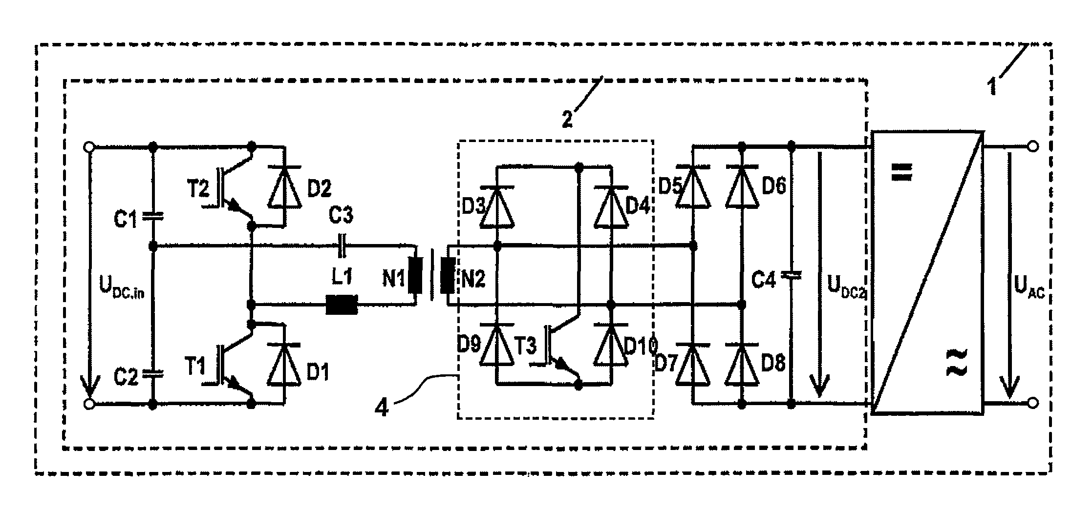
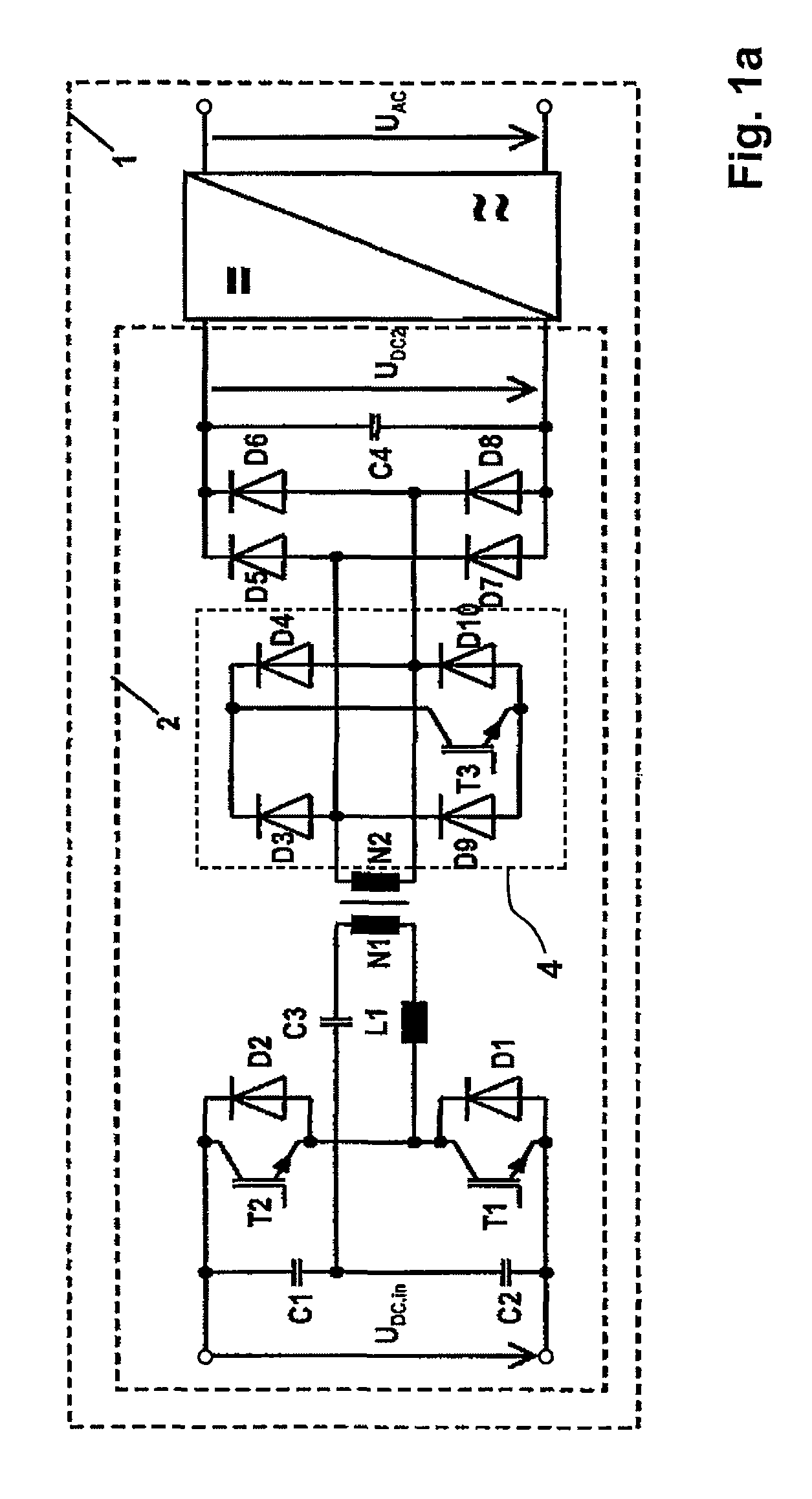
[0017]FIG. 1a shows a photovoltaic inverter 1 that includes a direct current-direct current (DC / DC) converter 2 and a direct current-alternating current (DC / AC) converter 3 with an output voltage UAC conforming to the grid. FIG. 1a shows in particular the DC / DC converter 2 operated in the resonant mode for converting a direct input voltage UDC in into a direct output voltage UDC2 with a bridge circuit on the input side. Herein, the bridge is shown as a half bridge, consisting of the two semi-conductor switches, preferably high-efficiency semi-conductor switches T1, T2, as well as of two capacitors C1, C2. It may also be configured to be a full bridge. There is further provided a resonance circuit with an high frequency (HF) transformer TR for galvanic separation. The resonance frequency is determined by a resonance inductance, in particular by a resonance choke L1, but also by the stray inductance of the HF transformer TR, and by a resonance capacitance, in particular a resonance ca...


PUM


Abstract

A direct current-direct current (DC / DC) converter operated in the resonant mode of operation for converting a direct input voltage into a direct output voltage with a bridge circuit located on the input side and incorporating switching elements, with a resonance circuit incorporating a resonance inductance and a resonance capacitance as well as with a high-frequency transformer for galvanic separation is disclosed, the transformer incorporates at least one primary winding and at least one secondary winding with at least two winding terminals each. The alternating current (AC) output of the bridge circuit is connected to the primary winding and a rectifier bridge with diodes to the secondary winding. A voltage boosting circuit array is connected downstream of the resonant circuit in such a manner that at least one additionally controllable switching element is contained, which is connected in parallel or in series to at least one additional diode or to at least one diode of the rectifier bridge on the secondary side, this array being connected in parallel to the high-frequency transformer so that the additional switching element short-circuits the resonance circuit in a triggered condition so that energy is stored in the resonance inductance and is delivered in the non-triggered condition.

Description

BACKGROUND OF THE INVENTION[0001]A direct current-direct current (DC / DC) converter of the generic type is known from DE 102005023291 A1. On its input side, this converter incorporates a boost converter as well as a resonance converter so that, practically, there are provided two DC / DC converters or energy converter stages. This DC / DC converter has the advantage that the load of the switches is reduced in the resonance converter. In the event of discontinuous current, the switches turn on and off almost without any loss thanks to the incorporated resonance. Another advantage is its galvanic isolation. Through DC-AC converter clocking, high capacitive leakage currents may occur in photovoltaic (PV) generators. Galvanic isolation makes it possible to ground the photovoltaic generator and to eliminate these undesired currents as a result thereof. The boost converter located on the input side permits raising fluctuating input voltages, in particular lower input voltages. The direct volta...

Claims


Application Information

Patent Timeline
Patent Type & Authority Patents(United States)
IPC IPC(8): H02M3/335
CPCH02M3/33576H02M2001/0058Y02B70/1491Y02B70/1433H02M1/0058H02M1/0085Y02B70/10H02M3/28
Inventor MALLWITZ, REGINEZACHARIAS, PETER
Owner SMA SOLAR TECH AG
Why Eureka
Try Eureka