Optical communication module

a communication module and optical communication technology, applied in the field of optical communication modules, can solve the problems of low production, low optical coupling efficiency, and severe optical/electrical crosstalk of conventional bidirectional optical transceiver modules thus configured, and achieve the effects of minimizing optical or electrical crosstalk, maximizing optical coupling efficiency, and reducing manufacturing costs

Inactive Publication Date: 2012-09-11
ELECTRONICS & TELECOMM RES INST
View PDF11 Cites 14 Cited by
  • Summary
  • Abstract
  • Description
  • Claims
  • Application Information

AI Technical Summary

Benefits of technology

[0010]The following description relates to an optical communication module which reduces the manufacturing cost, minimizes the optical or electrical crosstalk and maximizes the optical coupling efficiency.
[0014]According to the present invention, the optical communication module may be configured such that one of the light-emitting element of the optical transmitter and the light-receiving element of the optical receiver is first provided in a passive alignment manner and the other is provided in an active alignment manner. Accordingly, it is possible to reduce the number of the process steps and to save the module process cost.
[0015]Furthermore, the optical transmitter and the optical receiver may be provided in an active alignment manner. In addition, if the platform has a through-hole with an inclined inner sidewall, it is possible to improve the optical coupling efficiency.
[0016]Further, since the optical receiver and the optical transmitter may be separately provided on both sides of the platform, it is possible to minimize optical or electrical crosstalk. Accordingly, it may be applied to high-speed signal transmission.

Problems solved by technology

Since two TO-Can type packages are provided in an active alignment manner by the laser welder, the bidirectional optical transceiver module can obtain a maximum optical coupling efficiency but requires a number of process steps resulting in a low production.
However, the conventional bidirectional optical transceiver module thus configured may experience severe optical / electrical crosstalk since the optical transmitter and the optical receiver are provided on the top surface of the same substrate.
Furthermore, since the optical coupling is made using the inclined surface of V-groove of SiOB, the optical coupling efficiency may be low and the alignment tolerance may be small.
Further, since a photodiode chip of the optical receiver has such a small active region that the coupling efficiency between the optical receiver and the optical filter becomes lower, this type of a bidirectional optical transceiver module is not appropriate for high-speed signal transmission.

Method used


Image

  • Optical communication module
  • Optical communication module
  • Optical communication module

Examples


first embodiment

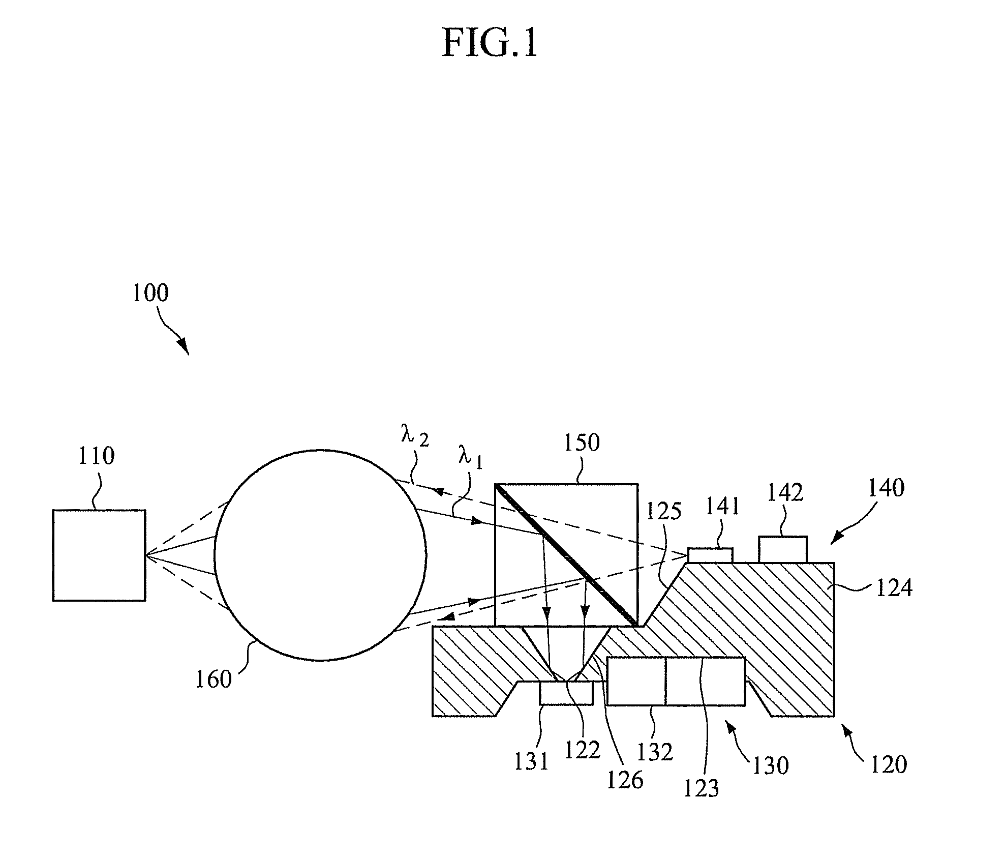
[0035]FIG. 1 is a cross-sectional view of an optical communication module according to the present invention.

[0036]Referring to FIG. 1, an optical communication module 100 may transmit and receive light in both directions at the same time. The optical communication module 100 includes an optical line 110, a platform 120, an optical receiver 130, an optical transmitter 140, an optical filter 150 and an optical line focusing lens 160. The optical line focusing lens 160 may be mounted on a package rather than on the platform 120.

[0037]The optical line 110 may be an optical fiber or a stub for optical communication. The optical line 110 may receive light λ1 from outside and transmit it to the optical receiver 130. Further, the optical line 110 may receive light λ2 from the optical transmitter 140 and transmit it to the outside.

[0038]The platform 120 is provided at one side of the optical line 110. The platform 120 may partly have depressed and flat portions at its top and bottom surface...

second embodiment

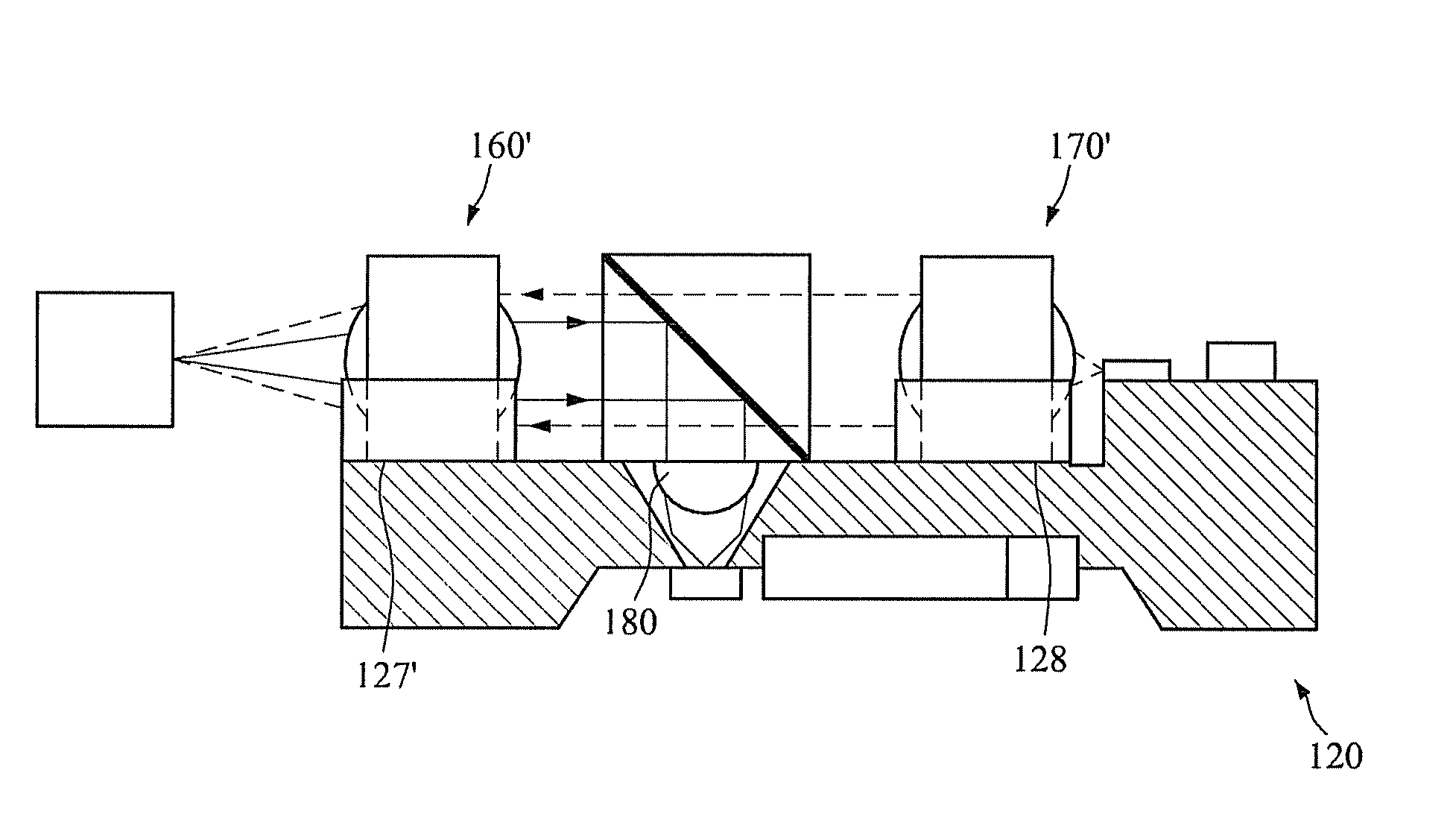
[0061]FIG. 10 is a cross-sectional view of an optical communication module according to the present invention. Like reference numerals denote like elements and a detailed description thereof will thus be omitted herein.

[0062]Referring to FIG. 10, an optical communication module 200 is configured such that an optical line focusing lens 260 is provided between the light-emitting element 141 and the optical filter 150. The optical line focusing lens 260 focuses light from the light-emitting element 141 and transmits it to the optical line 110 through the optical filter 150. The optical line focusing lens 260 may be an aspheric lens as shown in FIG. 10. However, the optical line focusing lens 260 may be a ball lens or a half-ball lens and may be placed on a groove which is formed on the platform 120 as described above.

[0063]The optical filter 150 may be implemented in such ways as described above. For another example, the light-emitting element 141 may be provided on the bottom surface ...

third embodiment

[0064]FIG. 11 is a cross-sectional view of an optical communication module according to the present invention.

[0065]Referring to FIG. 11, an optical communication module 300 is configured in a triplexer form to make bidirectional communication with a single optical line 110.

[0066]The optical communication module 300 includes at least one additional through-hole 322 and one additional optical filter 350. Like the through-hole 122, the additional through-hole 322 is formed to vertically pass through the platform 120. The additional through-hole 322 is arranged next to the through-hole 122 in parallel with the direction of light input and output through the optical line 110. The additional through-hole 322 may have the same configuration as the through-hole 122.

[0067]The additional optical filter 350 is provided on the platform 120 to correspond to the additional through-hole 322. The additional optical filter 350 has a different wavelength pass band than the optical filter 150 which i...


PUM


Abstract

An optical communication module which uses a single optical fiber to enable bidirectional communication or multiplexing communication is provided. The optical communication module includes a platform configured to have a through-hole therein which vertically passes through the platform; an optical receiver configured to be provided on the platform and include a light-receiving element; an optical transmitter configured to be provided on the platform and include a light-emitting element; and an optical filter configured to be provided on one surface of the platform to correspond to the through-hole, transmit light from the light-emitting element to an optical line, and transmit light input through the optical line to the light-receiving element, where one of the light-receiving element and the light-emitting element is provided on one surface of the platform on an opposite side of the optical line with the optical filter interposed therebetween, and the other is provided on the other surface of the platform to correspond to the through-hole. Accordingly, it is possible to reduce the manufacturing cost, minimize the optical or electrical crosstalk, and maximize the optical coupling efficiency.

Description

CROSS REFERENCE TO RELATED APPLICATION[0001]This application claims the benefit under 35 U.S.C. §119(a) of Korean Patent Application No. 10-2009-0078261, filed on Aug. 24, 2009, the disclosure of which is incorporated by reference in its entirety for all purposes.BACKGROUND[0002]1. Field[0003]The following description relates to an optical communication module, and more particularly, to an optical communication module which uses a single optical fiber to make bidirectional communication or multiplexing communication.[0004]2. Description of the Related Art[0005]A conventional bidirectional optical transceiver module is typically configured such that an optical filter is provided in a metal housing and a TO-Can type optical transmitter package and a TO-Can type optical receiver package are provided in an active alignment manner and fixed to the metal housing by a laser welder.[0006]Since two TO-Can type packages are provided in an active alignment manner by the laser welder, the bidir...

Claims


Application Information

Patent Timeline
Patent Type & Authority Patents(United States)
IPC IPC(8): H04B10/00H04B10/2581
CPCG02B6/4246H04B10/40H04B10/2581H04B10/00
Inventor LIM, KWON-SEOBKANG, HYUN SEOKOH, JAI SANG
Owner ELECTRONICS & TELECOMM RES INST
Why Eureka
Try Eureka