
Composite cemented carbide rotary cutting tools and rotary cutting tool blanks

a technology of cemented carbide and rotary cutting tools, which is applied in the direction of shaping cutters, manufacturing tools, twist drills, etc., can solve the problems of reducing the service life of rotary cutting tools

Active Publication Date: 2012-09-25
KENNAMETAL INC
View PDF555 Cites 20 Cited by
  • Summary
  • Abstract
  • Description
  • Claims
  • Application Information

AI Technical Summary

Benefits of technology

The present patent is about a new type of composite article that can be used in rotary cutting tools. This composite article includes an elongated portion made up of two different cemented carbides: a first region made of a first cemented carbide, and a second region made of a second cemented carbide. The second cemented carbide is a hybrid cemented carbide that includes a dispersed phase and a continuous phase, with at least 0.5 percent by weight of cubic carbide based on the weight of the hybrid cemented carbide. This new composite article has improved chemical wear resistance compared to traditional cemented carbides. The patent also describes a method for producing this new composite article by preparing a hybrid cemented carbide blend and consolidating it with a metallurgical powder. Overall, this patent provides a new solution for improving the performance of rotary cutting tools.

Problems solved by technology

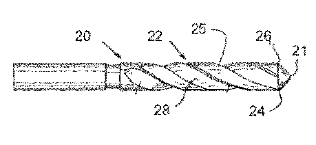
The monolithic construction of rotary cutting tools inherently limits their performance and range of application.
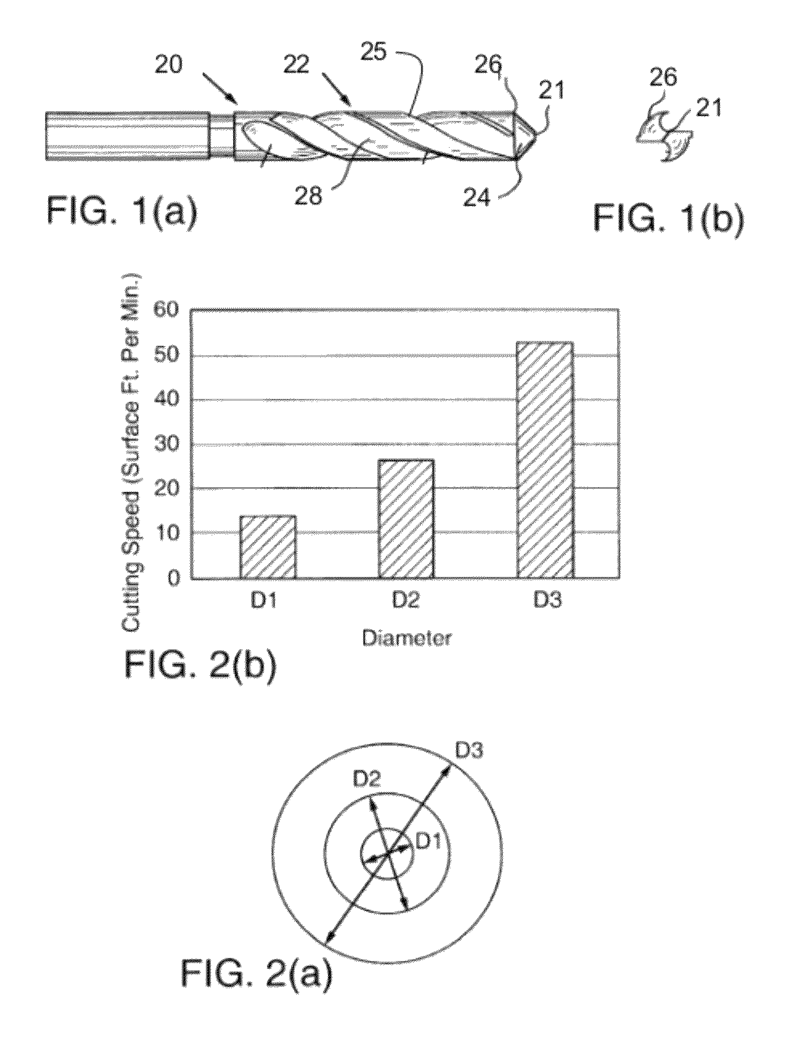
Because of these variations in cutting speed, drills and other rotary cutting tools having a monolithic construction will not experience uniform wear at different points ranging from the center to the outside edge of the tool's cutting surface, and chipping and / or cracking of the tool's cutting edges may occur.
Therefore, the chisel edge of conventional non-hybrid drills of monolithic construction used in drilling casehardened materials will wear at a much faster rate than the remainder of the cutting edge, resulting in a relatively short service life for such drills.
In both instances, because of the monolithic construction of conventional non-hybrid cemented carbide drills, frequent regrinding of the cutting edge is necessary, thus placing a significant limitation on the service life of the drill.
Frequent regrinding and tool changes also result in excessive downtime for the machine tool that is being used.
Other types of rotary cutting tools having a monolithic construction suffer from similar deficiencies.
As with regular twist drills, the service life of step and subland drills of a conventional non-hybrid monolithic cemented carbide construction may be severely limited because of the vast differences in cutting speeds experienced at the drills' different cutting edge diameters.
The limitations of monolithic rotary cutting tools are also exemplified in end mills.
In general, end milling is considered an inefficient metal removal technique because the end of the cutter is not supported, and the length-to-diameter ratio of end mills is usually large (usually greater than 2:1).
This causes excessive bending of the end mill and places a severe limitation on the depths of cut and feed rates that can be employed.
This method of producing hardened drills has major limitations.
First, the hardened surface layer of the drills is extremely thin and may wear away fairly quickly to expose the underlying softer cemented carbide.
Second, once the drills are redressed, the hardened surface layer is completely lost.
Third, the decarburization step, which is an additional processing step, significantly increases the cost of the finished drill.
Those grades, however, may not be suitable for machining steel alloys due to a reaction that can occur between iron in the steel workpiece and tungsten carbide in the rotary cutting tool.
The addition of cubic carbides in such tools, however, generally results in a decrease in tool strength.

Method used


Image

  • Composite cemented carbide rotary cutting tools and rotary cutting tool blanks
  • Composite cemented carbide rotary cutting tools and rotary cutting tool blanks
  • Composite cemented carbide rotary cutting tools and rotary cutting tool blanks

Examples


example 1

[0091]FIG. 7 is a micrograph of a region 60 of a rotary tool blank comprising a hybrid cemented carbide including cubic carbide according to the present disclosure. The region depicted in FIG. 7 comprises a hybrid cemented carbide grade including 20 percent by volume of Firth Grade T-04 cemented carbide as the dispersed phase 62. Firth Grade T-04 cemented carbide comprises 6% by weight of a solid solution of the cubic carbides TiC, TaC, and NbC, 82% by weight of WC, and 12% by weight Co. The continuous phase 64 of the hybrid cemented carbide region of the rotary cutting tool blank shown in FIG. 7 comprises 80 percent by volume of Firth Grade 248 cemented carbide. Firth Grade 248 cemented carbide comprises 89% by weight of WC and 11% by weight of Co. The measured contiguity ratio of the dispersed phase 62 is 0.26 and, thus, is less than 0.48. All cemented carbide powders were obtained from ATI Firth Sterling, Madison, Ala.

example 2

[0092]The hybrid cemented carbide region 60 of the rotary tool blank depicted in FIG. 7 of Example 1 was prepared by presintering the Firth Grade T-04 cemented carbide granules (or powder) at a temperature of 800° C. in a vacuum. The presintered Firth Grade T-04 cemented carbide granules comprise the dispersed phase 62 of the hybrid cemented carbide region depicted in FIG. 7. The presintered granules were blended with green granules of Firth Grade 248 to form a hybrid cemented carbide blend. The hybrid cemented carbide blend was placed in a void in a mold and compacted at a pressure of 137.9 MPa (20,000 psi) by mechanical pressing. It is understood that isostatic pressing can be used for the same result. The hybrid cemented carbide compact was over-pressure sintered in a sinter hot isostatic pressing (sinter-HIP) furnace at 1400° C.

example 3

[0093]A region 70 of a tool blank comprising a hybrid cemented carbide comprising cubic carbide according to the present disclosure is seen in the micrograph of FIG. 8. The hybrid cemented carbide shown in FIG. 8 includes 20 percent by volume ATI Firth Sterling Grade 248 cemented carbide as the dispersed phase 72 and 80 percent by volume ATI Firth Sterling Grade T-04 cemented carbide (with 6% by weight cubic carbide) as the continuous phase 74. The contiguity ratio of the dispersed phase is 0.40. The hybrid cemented carbide region of the tool blank was prepared using a process and conditions similar to Example 2.


PUM

PropertyMeasurementUnit
particle sizeaaaaaaaaaa
diameters D1aaaaaaaaaa

Abstract

Composite articles, including composite rotary cutting tools and composite rotary cutting tool blanks, and methods of making the articles are disclosed. The composite article includes an elongate portion. The elongate portion includes a first region composed of a first cemented carbide, and a second region autogenously bonded to the first region and composed of a second cemented carbide. At least one of the first cemented carbide and the second cemented carbide is a hybrid cemented carbide that includes a cemented carbide dispersed phase and a cemented carbide continuous phase. At least one of the cemented carbide dispersed phase and the cemented carbide continuous phase includes at least 0.5 percent by weight of cubic carbide based on the weight of the phase including the cubic carbide.

Description

BACKGROUND OF THE TECHNOLOGY[0001]1. Field of the Technology[0002]The present invention is generally directed to rotary cutting tools and rotary cutting tool blanks having a composite construction including regions of differing composition and / or microstructure, and to related methods. The present invention is more particularly directed to multi-grade cemented carbide rotary cutting tools and tool blanks for rotary cutting tools having a composite construction wherein at least one region comprises a hybrid cemented carbide including cubic carbide, and to methods of making the rotary cutting tools and rotary cutting tool blanks. The present invention finds general application to rotary cutting tools such as, for example, tools adapted for drilling, reaming, countersinking, counterboring, and end milling.[0003]2. Description of the Background of the Technology[0004]Cemented carbide rotary cutting tools (i.e., cutting tools driven to rotate) are commonly employed in machining operation...

Claims


Application Information

Patent Timeline
Patent Type & Authority Patents(United States)
IPC IPC(8): B23B27/14B23B51/02
CPCB22F7/062C22C1/051C22C29/06B22F2005/001Y10T408/9097Y10T408/78Y10T407/26Y10T407/27Y10T407/1946C22C1/05B23B27/14B23B51/00
Inventor MIRCHANDANI, PRAKASH K.
Owner KENNAMETAL INC
Learn More