Compacted air flow rapid fluid evaporation system

a fluid evaporation and compressed air technology, applied in the direction of liquid degasification, separation process, filtration separation, etc., can solve the problems of high maintenance cost, high per-unit high cost of distilled water, etc., to achieve cost-effective production and operation, less space, and more efficient

Active Publication Date: 2012-09-25
MICRONIC TECH
View PDF33 Cites 12 Cited by
  • Summary
  • Abstract
  • Description
  • Claims
  • Application Information

AI Technical Summary

Benefits of technology

[0014]The invention disclosed herein offers a desalination system that includes what can be considered a compacted air flow rapid fluid evaporation system. Compared to existing technologies, the present invention is simpler, requires less space, and is more efficient and cost effective to produce and operate.

Problems solved by technology

Maintenance costs are high because the distillation apparatus is metal and salt water causes corrosion.
Additionally, distillation is inherently thermodynamically inefficient due to energy losses in the process.
Therefore the per-unit cost of distilled water is high.
Reverse osmosis is negatively affected by chlorinated water or other chemicals and requires frequent and expensive maintenance.
Reverse osmosis also suffers from membrane vulnerabilities that risk rupture or explosion.
Researchers have documented many disadvantages of reverse osmosis, including:The membranes are sensitive to abuse and deterioration.The feed water usually needs to be pretreated to remove particulates (in order to prolong the life of the membrane).There may be interruptions of service during stormy weather (which may increase particulate resuspension and the amount of suspended solids in the feed water) for processing plants that use seawater.An extensive spare parts inventory must be maintained.There is a risk of bacterial contamination of the membranes; while bacteria are retained in the brine stream, bacterial growth on the membrane itself can introduce tastes and odors into the water.
This medical device does not relate to water desalination and is not intended to evaporate a liquid.

Method used


Image

  • Compacted air flow rapid fluid evaporation system
  • Compacted air flow rapid fluid evaporation system
  • Compacted air flow rapid fluid evaporation system

Examples


Embodiment Construction

[0060]Illustrative embodiments and aspects are described below. It will of course be appreciated that in the development of any such actual embodiment, numerous implementation-specific decisions must be made to achieve the specific goals of the developer, such as compliance with system-related and business-related constraints that will vary from one implementation to another. Moreover, it will be appreciated that such a development effort might be complex and time-consuming, but would nevertheless be a routine undertaking for those of ordinary skill in the art having the benefit of this disclosure.

[0061]Presently preferred embodiments of the invention are described below with reference to the accompanying drawings. Those skilled in the art will understand that the drawings are diagrammatic and schematic representations of presently preferred embodiments, and should not limit the scope of the claimed invention.

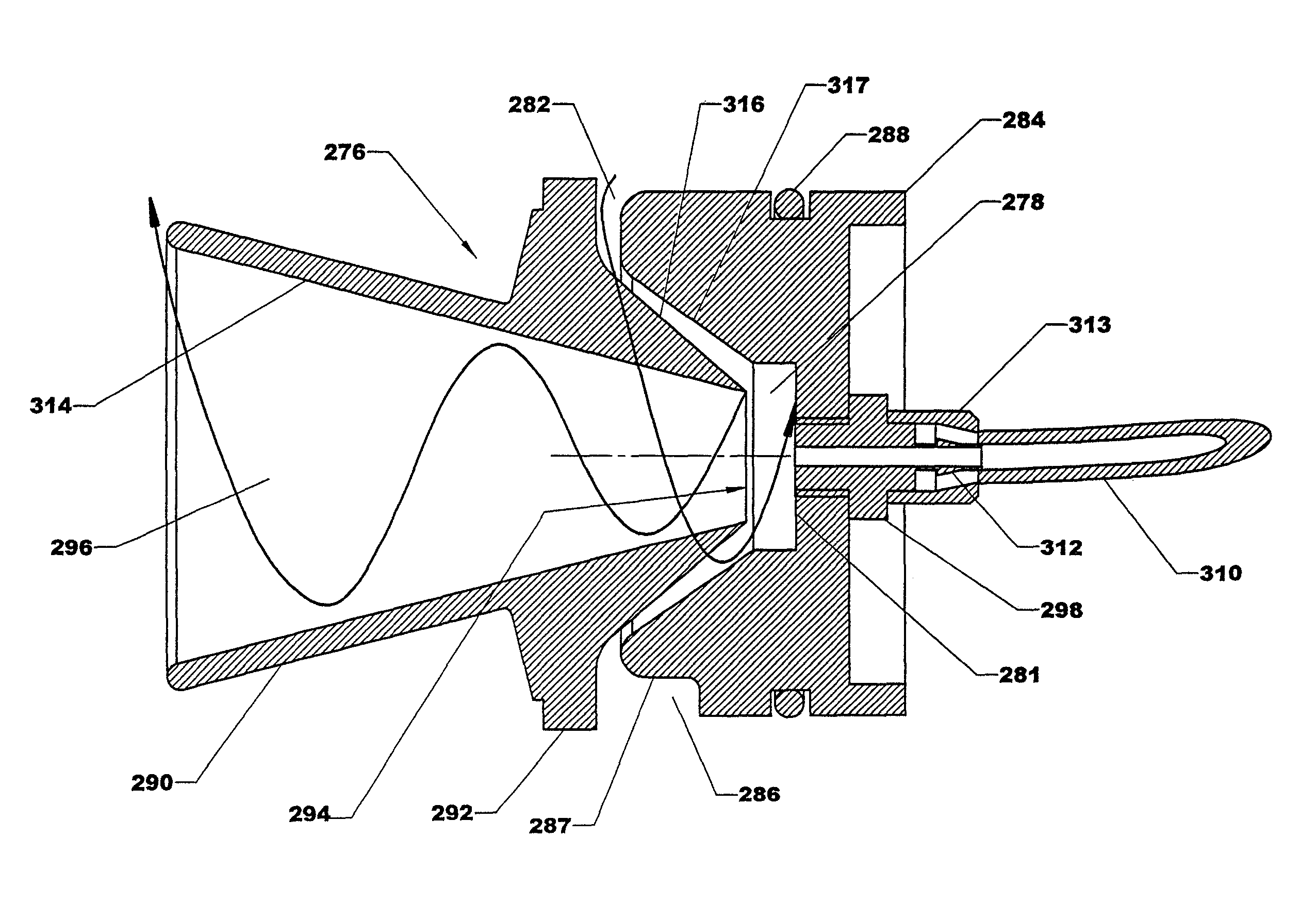
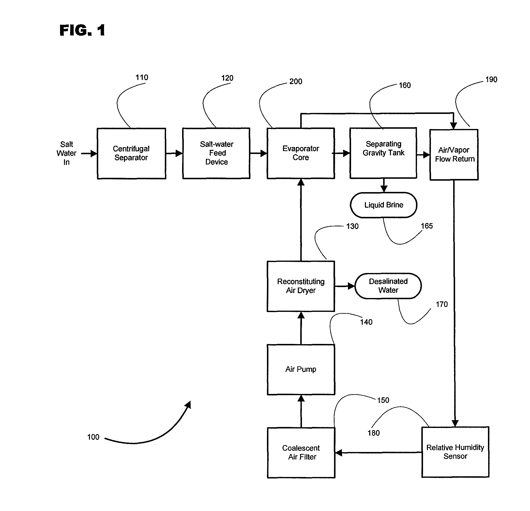
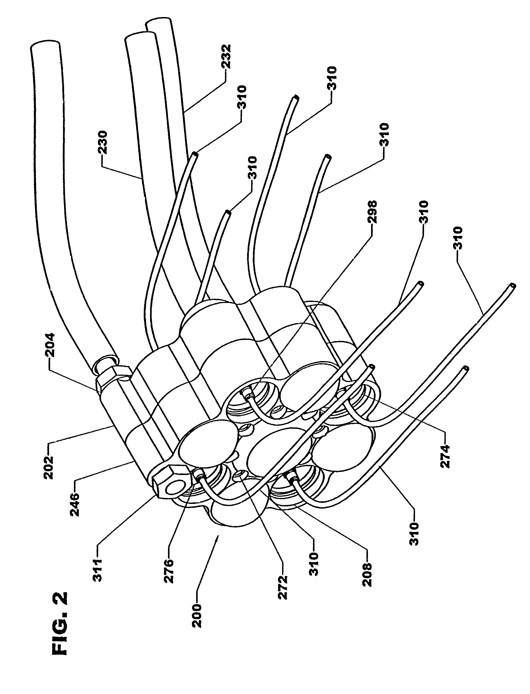
[0062]According to FIG. 1, there are eight subsystems that make up the ent...


PUM

PropertyMeasurementUnit
rotational velocityaaaaaaaaaa
helical shapeaaaaaaaaaa
temperaturesaaaaaaaaaa

Abstract

A total water desalination system is disclosed that includes a centrifugal separator, a feed-water device controlled by a relative humidity sensor, an air pump, an evaporator core, an air dryer, a non-particulate coalescent air filter, and an air flow / brine gravity separating tank. The evaporator core typically contains multiple conical processing chambers and introduces a physical dynamic that increases the surface area of the water, using low-level thermal energy to vaporize micron-size water particles into a gaseous state, suitable for reconstitution into desalinated (or lower salt content) water. The evaporator core operation principles are based on creating a highly dynamic environment that separates impurities from sea, brackish, river, or turbid water; evaporating the water into a residual clean vapor, and returning the vapor to water composition with high efficiency.

Description

BACKGROUND OF THE INVENTION[0001]1. Field of the Invention[0002]The present invention relates to a desalination system comprising a compact mechanical evaporator core integrated with a number of system components and an air input and discharge output. The device is designed to efficiently process salted, turbid, or silted water into desalinated and clean water.[0003]2. Discussion of the Related Art[0004]Distillation of water is the oldest used method of desalination. Distillation uses relatively high temperatures (over the boiling point) to turn water into steam and recondenses the steam into water through cooling. The higher the purity of the water needed, the more distillation is required. Distillation operates on the principle of reducing the vapor pressure of the water within the distillation unit to permit boiling to occur at lower temperatures, without the use of additional heat. Distillation units routinely use designs that conserve as much thermal energy as possible by inter...

Claims


Application Information

Patent Timeline
Patent Type & Authority Patents(United States)
IPC IPC(8): B01D19/00
CPCB01D1/14B01D1/30B01D1/20B01D5/006C02F1/04B01D5/0003Y02A20/124
Inventor ROCK, KELLY P.
Owner MICRONIC TECH
Why Eureka
Try Eureka