DC-DC switching power supply with power factor correction
a technology of power factor correction and switching power supply, applied in the direction of electric variable regulation, process and machine control, instruments, etc., can solve the problems of difficult linear signal transmission, inability to realistically and realistically achieve the type of digital control circuit, etc., and achieve the effect of reducing size and cos
- Summary
- Abstract
- Description
- Claims
- Application Information
AI Technical Summary
Benefits of technology
Problems solved by technology
Method used
Image
Examples
first preferred embodiment
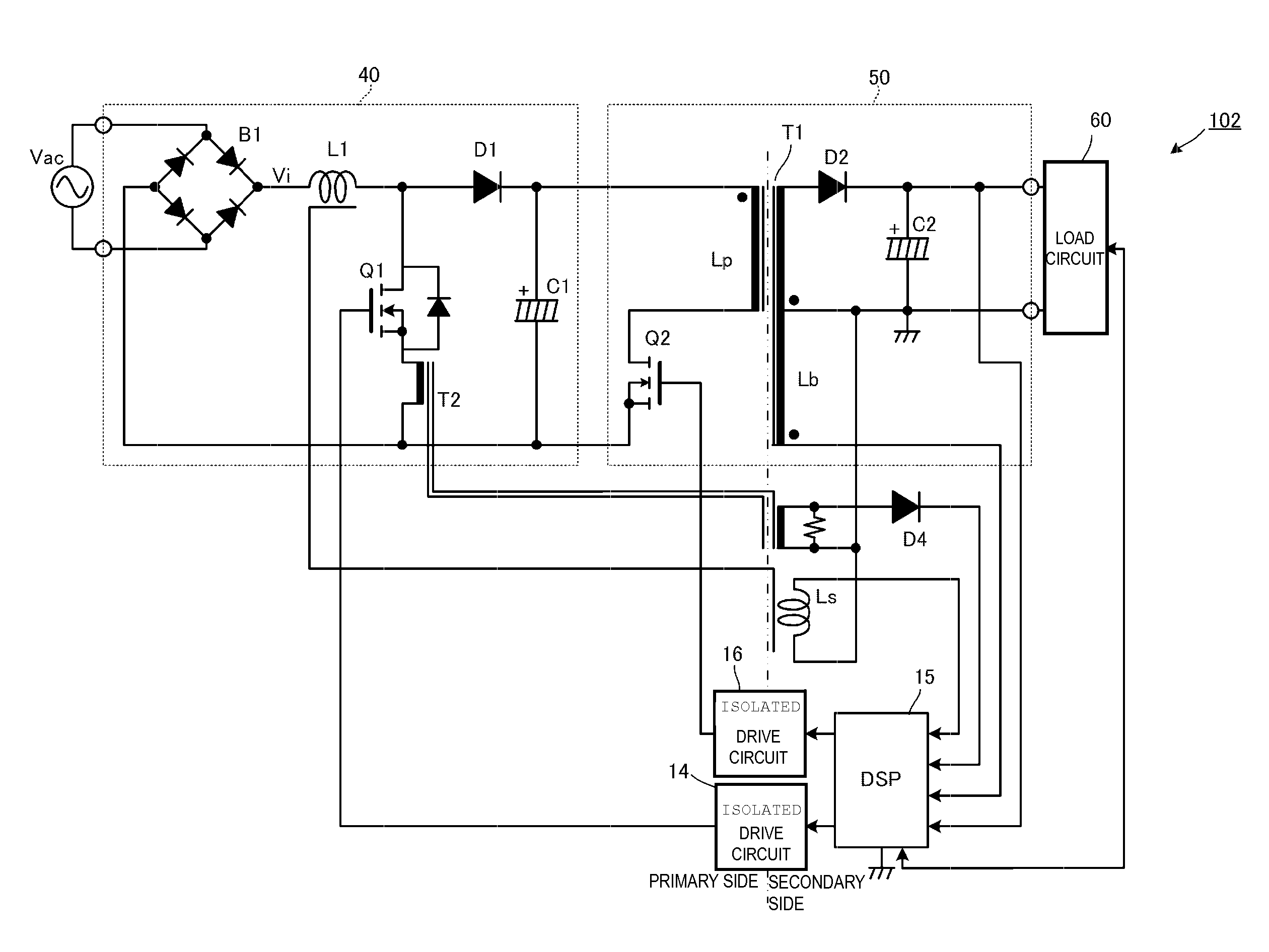
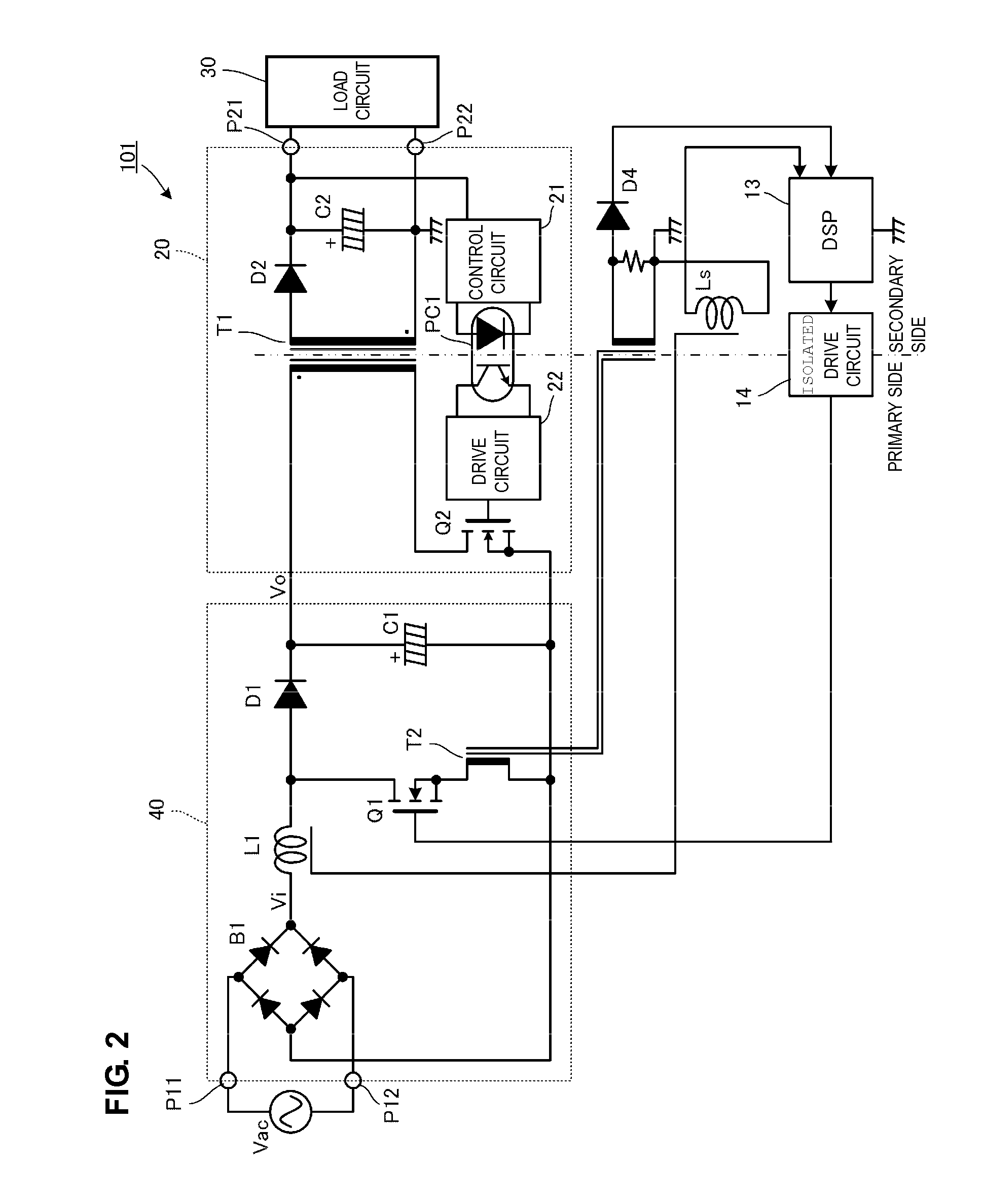
[0064]A switching power supply apparatus according to a first preferred embodiment of the present invention will be described with reference to FIGS. 2 to 8.
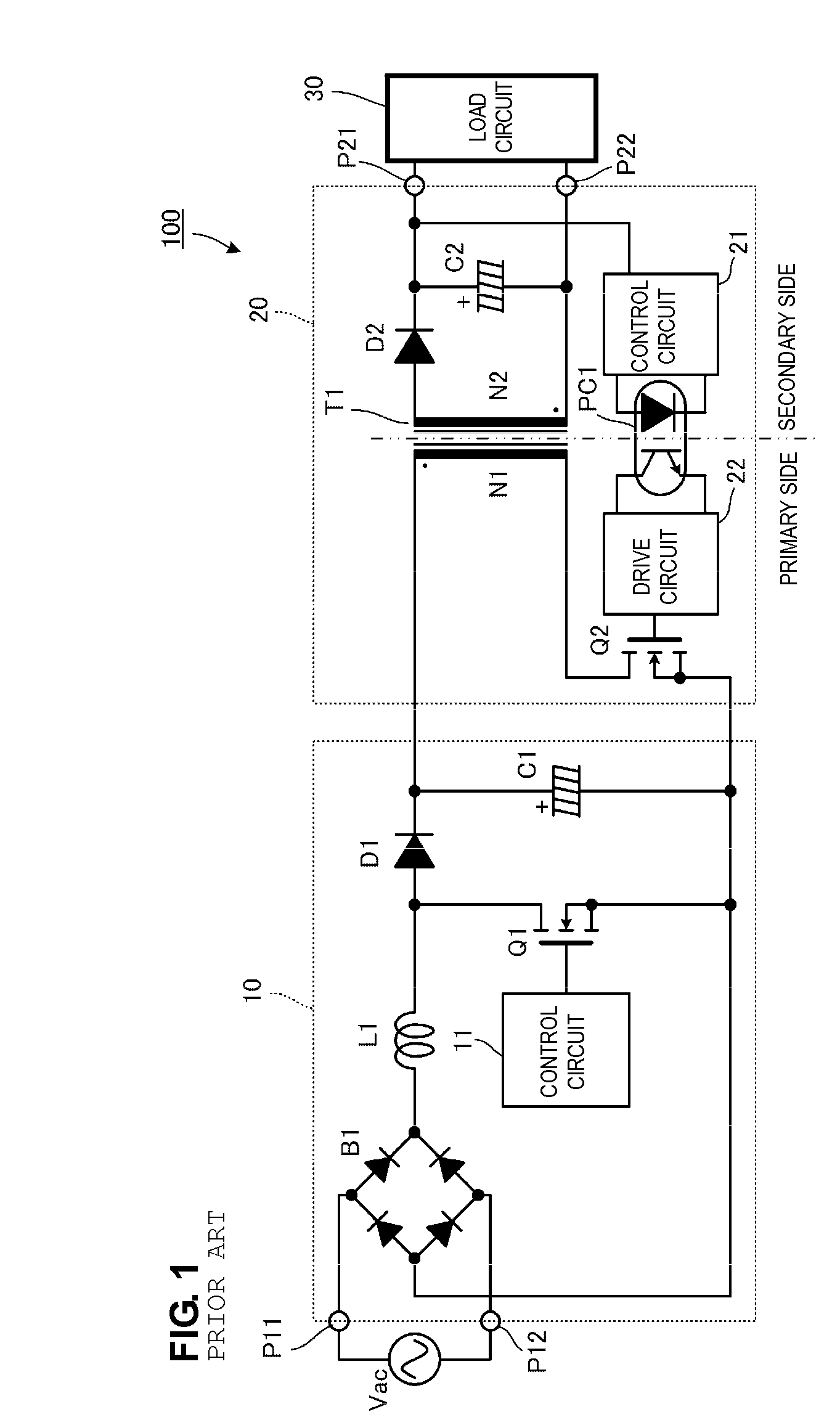
[0065]FIG. 2 is a circuit diagram illustrating a switching power supply apparatus 101 according to the first preferred embodiment. Unlike the circuit in the related art shown in FIG. 1, a digital signal processing circuit 13 defining a “digital control circuit” is included in a secondary side of an isolated DC-DC converter 20. The digital signal processing circuit 13 is preferably configured as a DSP, for example.
[0066]A primary side of a current transformer T2 is connected to a drain current path of a switching element Q1 included in a PFC converter 40. A secondary side of the current transformer T2 is connected to the digital signal processing circuit 13. Note that a diode D4 connected to the secondary side of the current transformer T2 is used to detect a current supplied between a drain and a source while a zero line is not ...
second preferred embodiment
[0095]FIG. 9 is a diagram illustrating a configuration of an inductor L1 and in the vicinity thereof included in a switching power supply apparatus according to a second preferred embodiment of the present invention. Other configurations are substantially the same as those shown in FIG. 2.
[0096]In the second preferred embodiment, a method for detecting a voltage Vo output from a PFC converter 40 will be described. Note that, in an example shown in FIG. 9, a pulse transformer T4 is disposed in the inductor L1 so that the output voltage Vo is obtained based on a voltage Vb on a secondary side of the pulse transformer T4.
[0097]Assuming that a winding ratio of a primary winding to a secondary winding of the pulse transformer T4 is denoted by np:ns, the voltage output from the pulse transformer T4 when a switching element Q1 is in an on state is also represented by Expression (3), and the voltage Vo output from the PFC converter is also calculated on the basis of Expression (5).
third preferred embodiment
[0098]FIG. 10 is a diagram illustrating a method for detecting a voltage input to a PFC converter and a voltage output from the PFC converter included in a switching power supply apparatus according to a third preferred embodiment of the present invention. A circuit configuration is substantially the same as that shown in FIG. 2.
[0099]In the third preferred embodiment, a voltage Vo output from a PFC converter 40 is detected based on an inclination of a current IL supplied to an inductor L1 shown in FIG. 10.
[0100]Here, when an inclination of the current IL when a switching element Q1 is in an on state (Ton) is denoted by ΔILon, an inclination in an off state (Toff) is denoted by ΔILoff, an input voltage is denoted by Vi, an output voltage is denoted by Vo, and an inductance of the inductor L1 is denoted by L, Expressions (7) and (8) below are obtained.
ΔILon=(Vi / L)Ton (7)
ΔILOff={(Vo−Vi) / L}Toff (8)
[0101]The values ΔILon, and ΔILOff can be obtained using drain currents IDb and IDp, th...
PUM
 Abstract
Description
Claims
Application Information
 - R&D
- Intellectual Property
- Life Sciences
- Materials
- Tech Scout
- Unparalleled Data Quality
- Higher Quality Content
- 60% Fewer Hallucinations
Browse by: Latest US Patents, China's latest patents, Technical Efficacy Thesaurus, Application Domain, Technology Topic, Popular Technical Reports.
© 2025 PatSnap. All rights reserved.Legal|Privacy policy|Modern Slavery Act Transparency Statement|Sitemap|About US| Contact US: help@patsnap.com


