Radiation phase contrast imaging apparatus

a contrast imaging and phase contrast technology, applied in imaging devices, instruments, applications, etc., can solve the problems of difficult to manufacture such narrow strips, difficult to adopt large-scale x-ray phase contrast imaging practically in medical diagnostic applications, and difficult to manufacture large-scale x-ray phase contrast imaging, etc., to improve manufacturing yield, reduce the size of periodic information imaging radiation image detectors, and facilitate manufacturing

Inactive Publication Date: 2012-10-02
FUJIFILM CORP
View PDF8 Cites 44 Cited by
  • Summary
  • Abstract
  • Description
  • Claims
  • Application Information

AI Technical Summary

Benefits of technology

[0064]According to a radiation phase contrast imaging apparatus of an embodiment of the present invention, a periodic information imaging radiation image detector having multiple linear electrodes is used, so that the detector may be manufactured easily. Further, the radiation emission unit and the periodic information imaging radiation image detector are disposed such that an extending direction of the linear electrodes of the periodic information imaging radiation image detector is perpendicular or parallel to a fan surface of the fan beam having a larger spread angle and the radiation emission unit is configured to scan the fan beam in the perpendicular direction. This allows large size view of radiation phase imaging to be performed.
[0071]According to a radiation phase contrast imaging apparatus of an embodiment of the present invention, the radiation emission unit and the first and second diffraction gratings are disposed such that an extending direction of diffraction members of the first and second diffraction gratings is parallel to a fan surface of the fan beam having a larger spread angle, and the radiation emission unit is configured to scan the fan beam in the perpendicular direction. This allows large size radiation phase imaging to be performed. Further, the second diffraction grating is configured to be shifted along an arc with a straight line connecting between the radiation source and the second diffraction grating as the radius, so that the blockage of radiation by the diffraction members of the second diffraction grating may be avoided.

Problems solved by technology

In this manner, It is difficult for X-rays emitted widely spread to pass through the diffraction gratings because the X-rays are incident from oblique directions.
It can be thought that the use of such a diffraction grating may possibly cause the problem described above.
Accordingly, large-size X-ray phase contrast imaging has been difficult to adopt practically in medical diagnostic applications.
It is difficult to manufacture such narrower strips.

Method used


Image

  • Radiation phase contrast imaging apparatus
  • Radiation phase contrast imaging apparatus
  • Radiation phase contrast imaging apparatus

Examples


first embodiment

[0158]Next, a modification of periodic information imaging radiation image detector 40 of radiation phase contrast imaging apparatus will be described.

[0159]In addition to first linear electrode group 81a and second linear electrode group 81b of periodic information imaging radiation image detector 40 shown in FIG. 10, constant potential linear electrode 90 may be provided in a grid pattern enclosing the charge collection electrode, constituted by first and second linear electrode groups 81a, 81b, of each unit element 72, as illustrated in FIG. 12. A spatial gap between charge collection electrodes induces phase component contamination because charges from out of linear electrode are collected by electric fields distortion. Consequently, the provision of constant potential linear electrode 90 to which a constant potential is applied allows stabilization of the electric fields and prevention of the contamination described above. A potential that does not cause a large potential diff...

second embodiment

[0179]As illustrated in FIGS. 20A to 20C, periodic information imaging radiation image detector 200 of the radiation phase contrast imaging apparatus includes the following stacked in the order listed below: first electrode layer 201 that transmits radiation; recording photoconductive layer 202 that generates charges by receiving radiation transmitted through first electrode layer 201; charge transport layer 204 that acts as an insulator against charges of one polarity of those generated in recording photoconductive layer 202 and as a conductor for charges of the other polarity; readout photoconductive layer 205 that generates charges by receiving readout light; and second electrode layer 206. Storage section 203 for storing charges generated in recording photoconductive layer 202 is formed adjacent to the interface between recording photoconductive layer 202 and charge transport layer 204. Each of the layers described above is stacked on glass substrate 207 one after another from ...

third embodiment

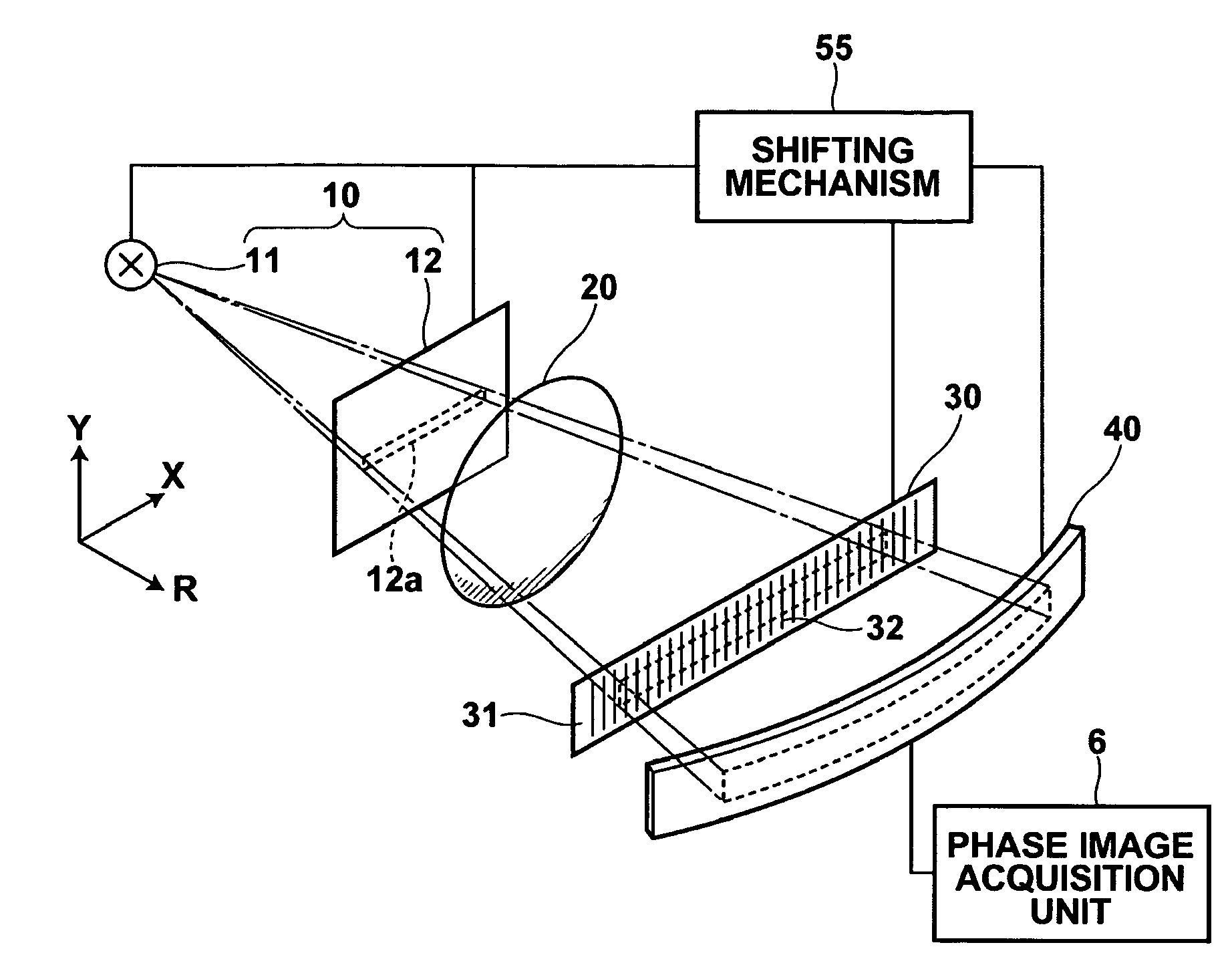
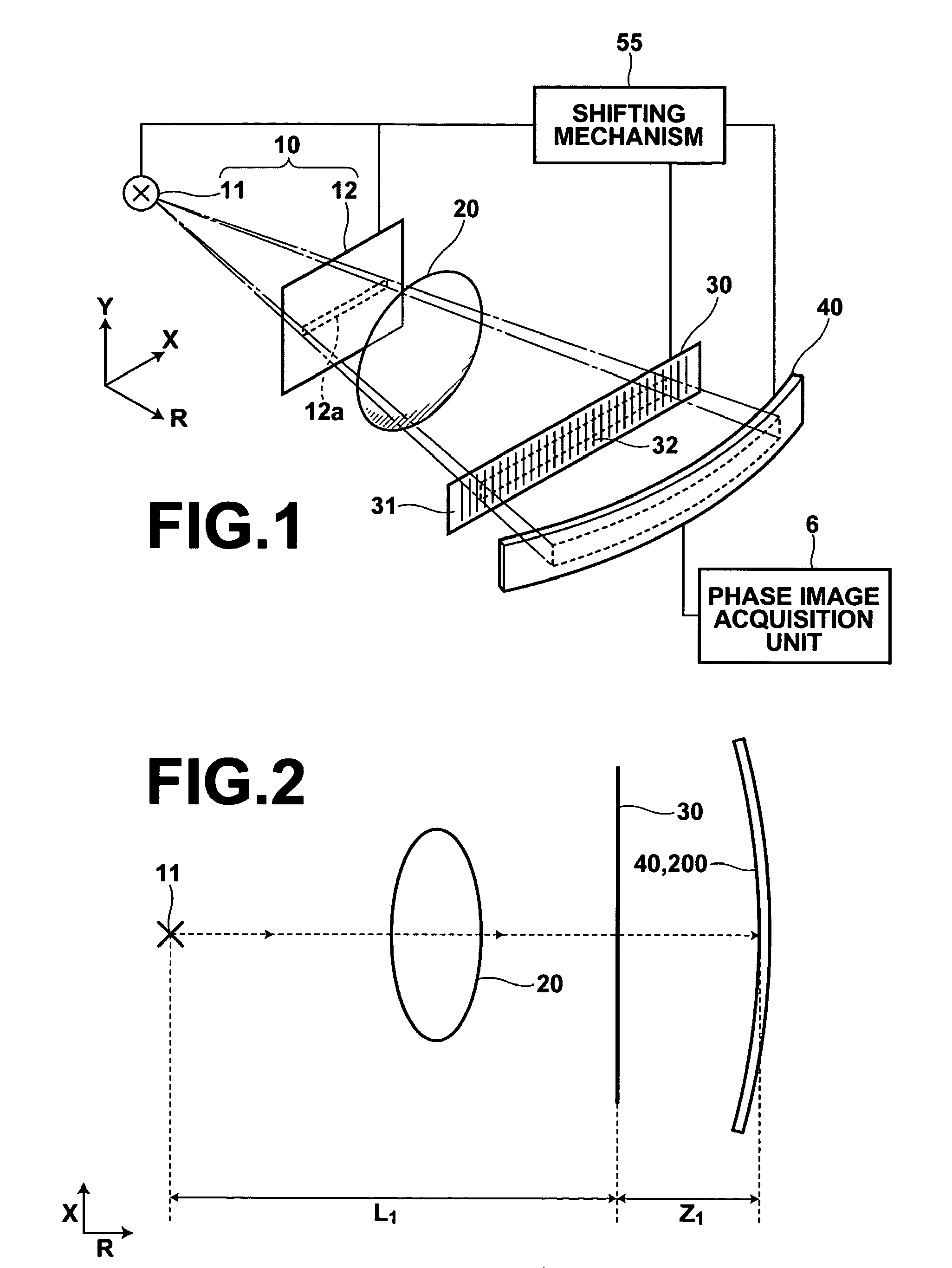
[0225]In the radiation phase contrast imaging apparatus of the third embodiment, as periodic information imaging radiation image detector 300 or diffraction grating 320 is shifted by shifting mechanism 56 at a predetermined pitch in Y direction, image recording in detector 300 and image signal reading from detector 300 are performed at each predetermined position, whereby image signals corresponding to the first and second phase components are detected at each predetermined position.

[0226]Then, slit member 12, diffraction grating 320, and periodic information imaging radiation image detector 300 are integrally shifted by a predetermined distance in Y direction by shifting mechanism 56 and the operation identical to that described above is repeated at the position.

[0227]Image signals detected in the manner as described above are inputted to phase image acquisition unit 6. Then, phase image acquisition unit 6 generates a phase image based on image signals of a plurality of phase compo...


PUM

PropertyMeasurementUnit
thicknessaaaaaaaaaa
thicknessaaaaaaaaaa
widthaaaaaaaaaa

Abstract

Providing a radiation emission unit that includes a radiation source and outputs a fan beam of radiation, a diffraction grating onto which radiation outputted from the radiation emission unit is emitted, and a periodic information imaging radiation image detector that includes multiple linear electrodes and detects periodic information of radiation diffracted by the diffraction grating, disposing the radiation emission unit and the periodic information imaging radiation image detector such that an extending direction of the linear electrodes of the periodic information imaging radiation image detector is perpendicular to a fan surface of the fan beam having a larger spread angle, and configuring the radiation emission unit to scan the fan beam in the perpendicular direction.

Description

CROSS-REFERENCE TO RELATED APPLICATIONS[0001]The present application claims priority from Japanese Patent Application No. 2009-109811, filed Apr. 28, 2009, the contents of which are herein incorporated by reference in their entirety.BACKGROUND OF THE INVENTION[0002]1. Field of the Invention[0003]The present invention relates to a radiation phase contrast imaging apparatus that employs a diffraction grating.[0004]2. Description of the Related Art[0005]An X-ray phase contrast imaging apparatus, which utilizes Talbot effect by a diffraction grating and Moire fringes in combination with another diffraction grating, i.e., X-ray Talbot interferometer has been studied as described, for example, in U.S. Pat. Nos. 5,812,629 and 7,180,979.[0006]U.S. Pat. Nos. 5,812,629 and 7,180,979 propose X-ray imaging apparatuses that include an X-ray source, two diffraction gratings, and an X-ray image detector, and in each apparatus the two diffraction gratings and X-ray image detector are planar shaped....

Claims


Application Information

Patent Timeline
Patent Type & Authority Patents(United States)
IPC IPC(8): G01N23/04
CPCA61B6/484A61B6/502A61B6/4291A61B6/4021G21K2207/005
Inventor TAKAHASHI, KENJI
Owner FUJIFILM CORP
Why Eureka
Try Eureka