Redox flow battery
a redox flow and battery technology, applied in the field of redox flow batteries, can solve the problems of difficulty in maintaining frequency and voltage, the operation of power systems, etc., and achieve the effect of suppressing precipitation and high electromotive for
- Summary
- Abstract
- Description
- Claims
- Application Information
AI Technical Summary
Benefits of technology
Problems solved by technology
Method used
Image
Examples
first experiment example
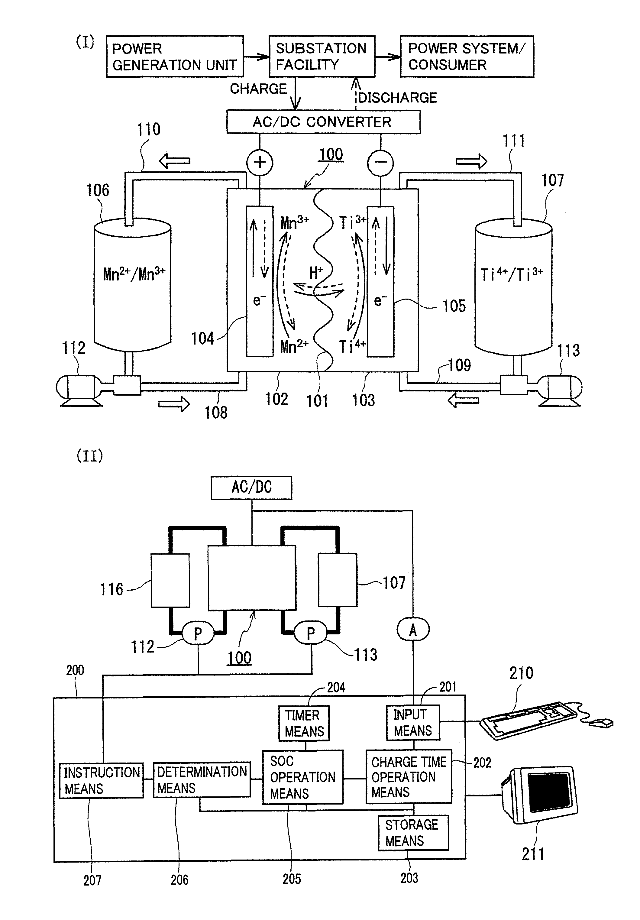
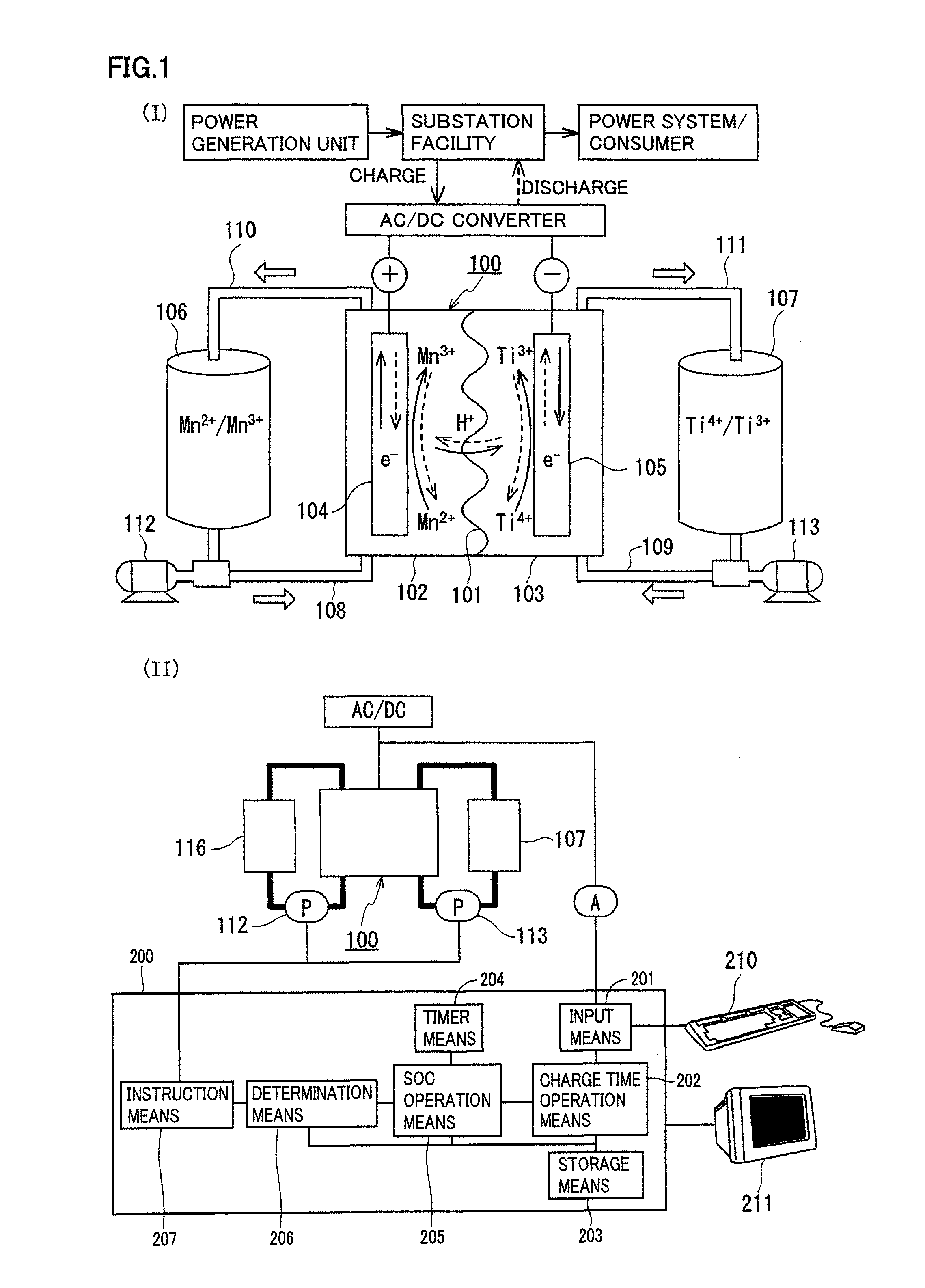
[0075]The redox flow battery system shown in FIG. 1 was structured, charged and discharged with an electrolyte containing a manganese ion for an active material as the positive electrode electrolyte, and relation between a state of charge (SOC) of the positive electrode electrolyte and a precipitation phenomenon was examined.
[0076]As the positive electrode electrolyte, an electrolyte having a manganese ion (divalent) concentration of 1M was prepared by dissolving manganese sulfate (divalent) in a sulfuric acid aqueous solution (H2SO4aq) having a sulfuric acid concentration of 4M. As the negative electrode electrolyte, an electrolyte having a vanadium ion (trivalent) concentration of 1.7M was prepared by dissolving vanadium sulfate (trivalent) in a sulfuric acid aqueous solution (H2SO4aq) having a sulfuric acid concentration of 1.75M. A carbon felt was used for each electrode, and an anion exchange membrane was used for the membrane.
[0077]In this experiment, a small cell in which an ...
second experimental example
[0085]A redox flow battery system was structured, charged and discharged in the same manner as the first experimental example, and battery properties (current efficiency, voltage efficiency, energy efficiency) were examined.
[0086]In this experiment, the negative electrode active material contained a metal ion different from that in the first experimental example. Specifically, as the negative electrode electrolyte, an electrolyte having a titanium ion (tetravalent) concentration of 1M was prepared by dissolving titanium sulfate (tetravalent) in a sulfuric acid aqueous solution (H2SO4aq) having a sulfuric acid concentration of 3.6M. The positive electrode electrolyte used was the same as that in the first experimental example (sulfuric acid concentration: 4M, manganese sulfate (divalent) was used, manganese ion (divalent) concentration: 1M). A carbon felt was used for each electrode, and an anion exchange membrane or a cation exchange membrane was used for the membrane.
[0087]As in th...
third experimental example
[0091]Solubility of a manganese ion (divalent) in sulfuric acid (H2SO4) was examined. The results are shown in FIG. 5. As shown in FIG. 5, it can be seen that the solubility of a manganese ion (divalent) decreases as sulfuric acid concentration increases, and the solubility is 0.3M when the sulfuric acid concentration is 5M. Conversely, it can be seen that high solubility of 4M is obtained in an area of low sulfuric acid concentration. The results show that, in order to increase manganese ion concentration in an electrolyte, particularly in order to obtain a practically desired concentration of not less than 0.3M, when a sulfuric acid aqueous solution is used as a solvent for the electrolyte, it is preferable to have a low sulfuric acid concentration of less than 5M.
PUM
| Property | Measurement | Unit |
|---|---|---|
| oxidation-reduction potentials | aaaaa | aaaaa |
| oxidation-reduction potentials | aaaaa | aaaaa |
| oxidation-reduction potential | aaaaa | aaaaa |
Abstract
Description
Claims
Application Information
 - R&D
- Intellectual Property
- Life Sciences
- Materials
- Tech Scout
- Unparalleled Data Quality
- Higher Quality Content
- 60% Fewer Hallucinations
Browse by: Latest US Patents, China's latest patents, Technical Efficacy Thesaurus, Application Domain, Technology Topic, Popular Technical Reports.
© 2025 PatSnap. All rights reserved.Legal|Privacy policy|Modern Slavery Act Transparency Statement|Sitemap|About US| Contact US: help@patsnap.com


