
Apparatus for measuring insulation characteristics of coated steel sheet

a technology of coating steel sheet and measuring apparatus, which is applied in the direction of air break switch, line transmission details, instruments, etc., can solve the problems of franklin tester, cast doubt on its usefulness in measuring insulation quality, uneven wear, etc., and achieve the effect of reducing the possibility of core failur

Inactive Publication Date: 2012-10-16
RAO DANTAM K
View PDF14 Cites 15 Cited by
  • Summary
  • Abstract
  • Description
  • Claims
  • Application Information

AI Technical Summary

Benefits of technology

"The present invention provides an apparatus for identifying defective insulation on punching or steel strips, reducing the possibility of core failure. The apparatus uses a continuous movement of a conductive cylindrical surface over the entire coated surface of a test specimen, measuring various metrics of quality of insulation such as surface resistivity, number of defects per square inch, breakdown voltage etc. The cylindrical electrode is soft or hard depending on its hardness, which affects the contact area and hence the contact pressure. The invention can be integrated into a coating line in a steel mill or electrical machinery manufacturing plant."

Problems solved by technology

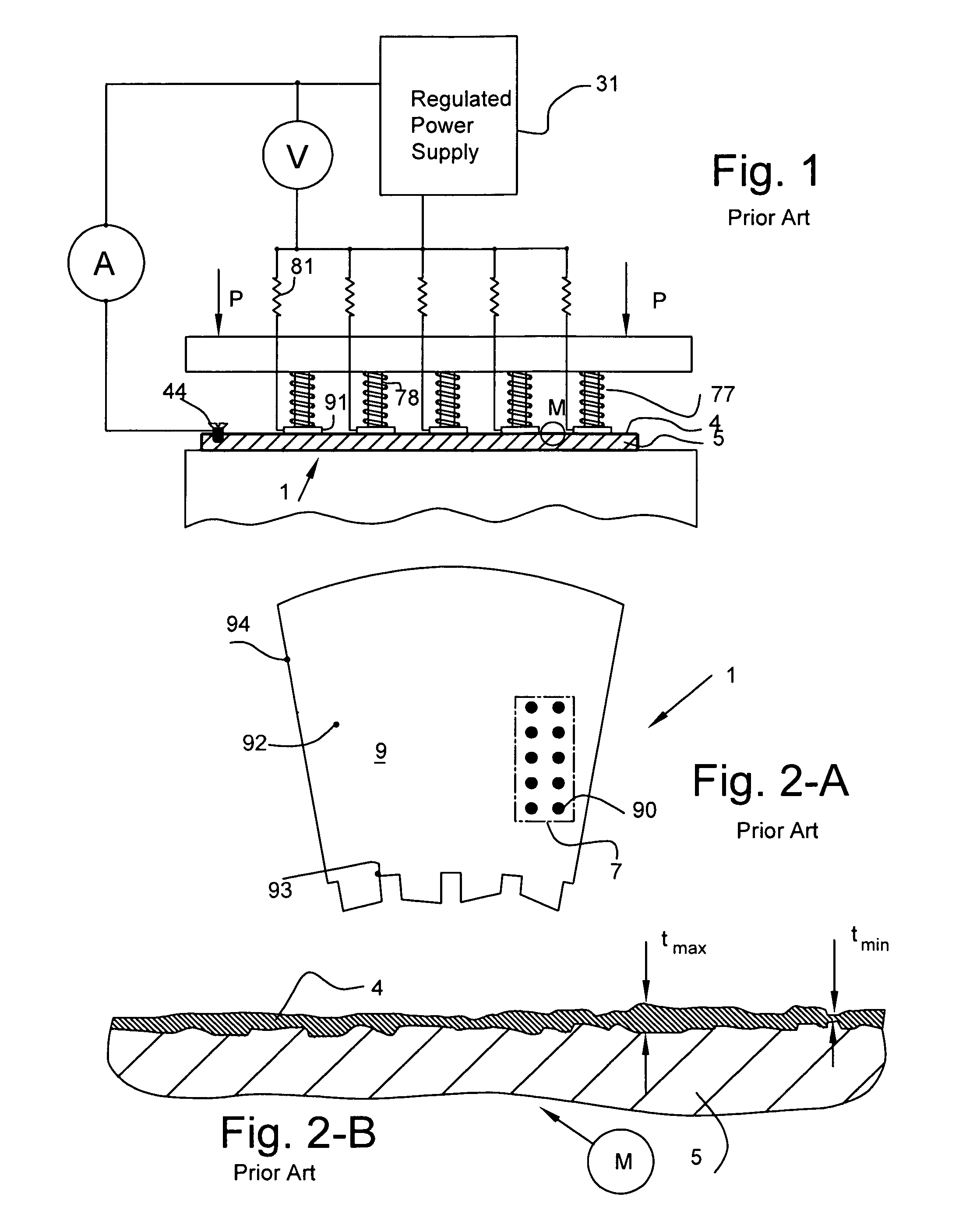
But several instances have been reported where Franklin current, measured by a steel mill's Franklin tester, is acceptable, but when measured by an electric machinery maker's Franklin Tester, is unacceptable.
Poor repeatability and reproducibility of its results have cast doubts on its usefulness in measuring the insulation quality of electrical steels per Godec (1982).
The prior art has attributed this non repeatability to unequal contact areas of the ten discrete button electrodes; this is believed to be caused by faulty alignment of the ten electrodes, unequal contact pressures exerted on ten different electrodes resulting in uneven wear etc.
Operating temperatures further degrade it.
Under combined stacking pressures and temperatures, coating can soften and become thinner, further reducing the surface resistivity.
But even after equalizing the contact area and accounting for pressure and temperature effects, Franklin Tester still suffers from several limitations.
One fundamental limitation is that it does not test the entire surface and hence is unable to detect shorts that may be present in untested areas of insulation which could lead to catostraphic core failure.
Other concerns include, but not limited to, not accounting for variations in surface resistivity from one location to another, limited ability to apply sufficiently large voltage typical in large machines, and lacking provisions to follow crowned profile of laminations.
These limitations resulted in Franklin tester's inability to distinguish between good quality insulation that can prevent core failure and bad quality insulation that can cause core failures, thereby rising questions about its usefulness.
Thus surface resistivity can vary by 50% or more depending on the location, and Franklin tester does not do a good job of accounting for this large variation, and it does not detect microscopic spots where there is no insulation and hence can cause electrical shorts.
While this low voltage suffices for testing small or medium sized machines, it may be too low to test the surface insulation in lamination used in large machines.
Hence the voltage applied by Franklin tester is significantly lower and inadequate to test laminations of large generators.
As a result, the core ends of such large machines are extremely vulnerable to failure by electrical shorts or bad quality insulation that is not detected by the Franklin tester.
This means that surface of lamination is not perfectly flat at any point, and is microscopically slanted.
This mismatch in flatness leads to different buttons contacting with different areas, thereby resulting in scatter in test results.
But ten tests only increase the tested area to about 10 in2, which still leaves 190 in2 or 95% of the insulated area untested.
Perhaps the most fundamental and serious limitation of Franklin tester is its inability to detect defective spots within the insulative coating that can create electrical shorts.
These defective spots are so small and microscopic that they cannot be seen by naked eye.
These surface insulation defects are very difficult to detect by naked eye, but they could cause havoc on the performance of the machine.
Such sharp amplification of eddy currents in confined and localized areas leads to concentrated heat; as this concentrated heat cannot be dissipated in confined areas, it leads to hot spots.
Surface insulation defects hence can lead to devastating core failure.
Published literature on generator core failures summarised below indicates that one major cause is interlaminar shorts caused by defects in the insulation coating.
In 1998, a 300 MW generator in San Antanio, Tex., overheated because of numerous interlaminar shorts and was removed from service leading to economic losses per Spisak (2004).
Thus even though the surface insulation in areas exposed to Franklin tester's contact buttons has high surface resistivity—as seen by low or near zero Franklin currents—defects in the surface insulation could lead to core failure.

Method used


Image

  • Apparatus for measuring insulation characteristics of coated steel sheet
  • Apparatus for measuring insulation characteristics of coated steel sheet
  • Apparatus for measuring insulation characteristics of coated steel sheet

Examples


embodiment 200

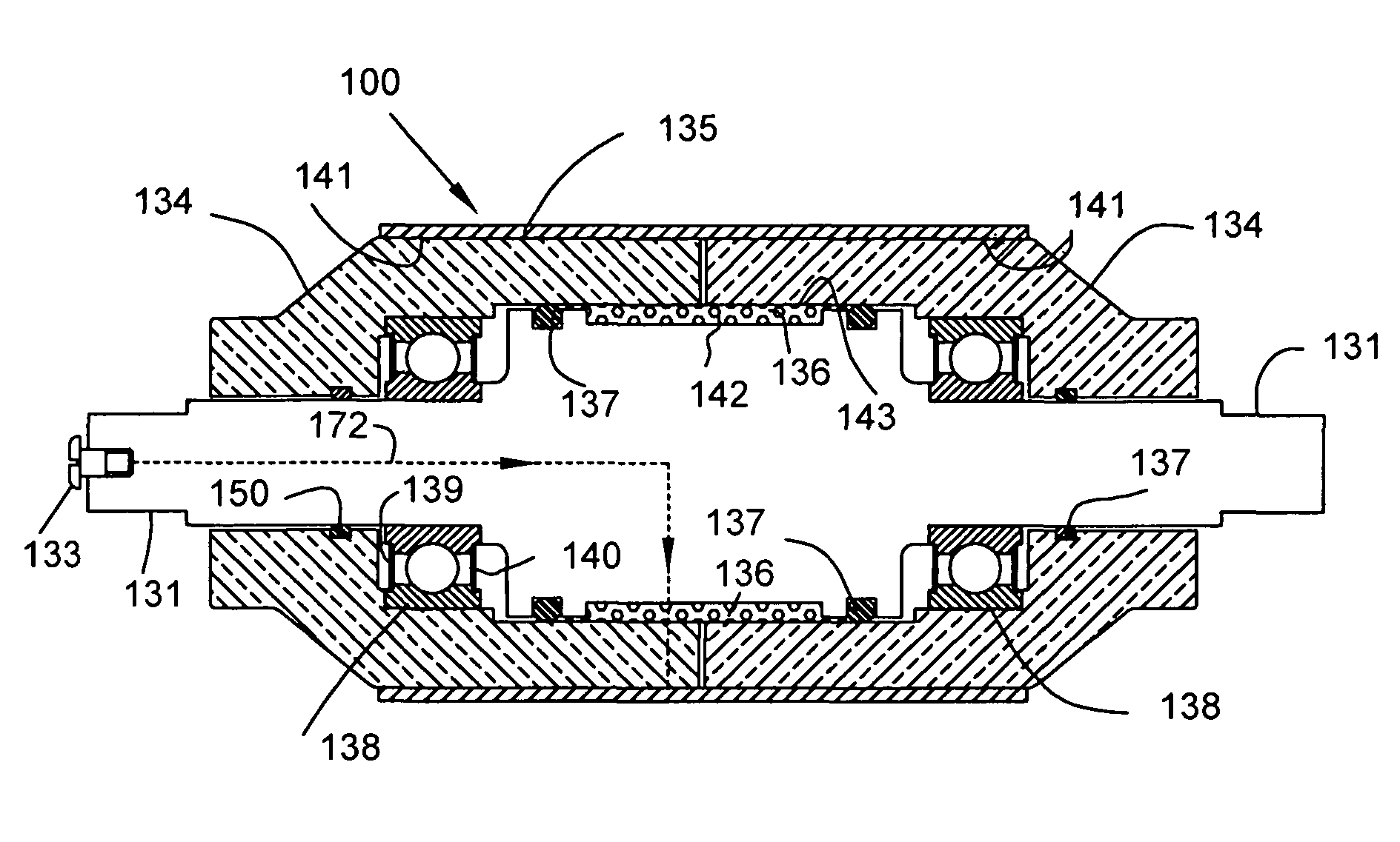
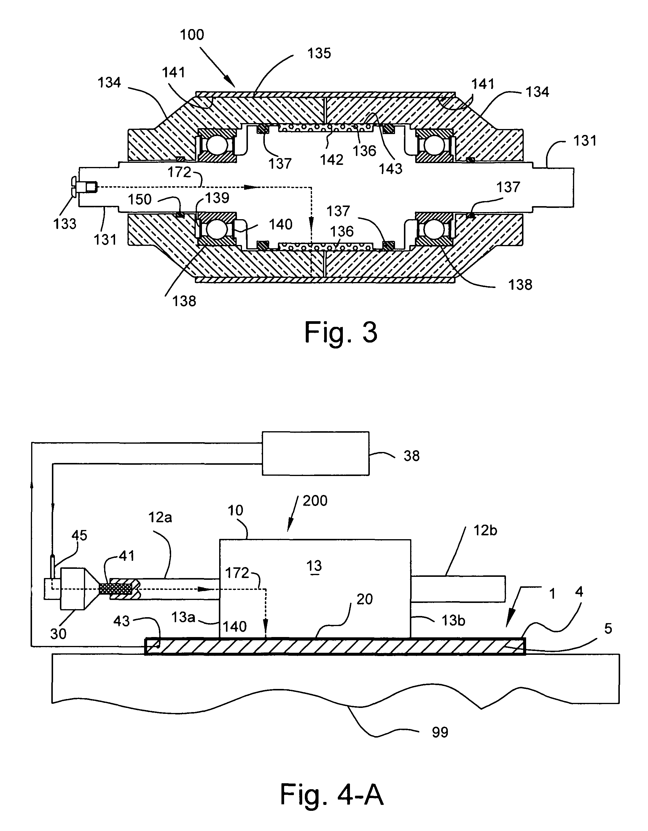
[0041]FIG. 4-A shows the schematic of an alternative embodiment 200 of the roving tester. This roving tester 200 comprises a cylindrical electrode 10, shafts 12a, 12b and a rotatable electrical connector (abbreviated as REC) 30, all located on the same axis of rotation. FIG. 4-A also shows the roving tester 200 resting on top of a test specimen 1. The test specimen 1 itself is attached to a flat worktable 99. The cylindrical electrode's round surface 13 makes a line contact 20 with the coating's surface 4. (in FIG. 4-A this line contact is shown as one line 20 for the sake of clarity). An electric circuit 38 applies a specified voltage across the terminal of REC 45 and a drill bit contact 43 electrically connected to the base metal 5 of the test specimen.

[0042]In the roving tester 200, cylindrical electrode 10 is preferably harder than that of test specimen 1, but it can be made softer without altering the invention. The round surface 13 of cylindrical electrode 10 is conductive and...

embodiment 300

[0048]FIG. 4-B shows an alternative embodiment 300 of roving tester which tests insulation on both sides 4a, 4b of steel strip or a lamination. This roving tester 300 is suitable for use with a coating line. After coating is applied on both sides of steel strip and fully cured, the steel strip or lamination 1 passes between two rollers 25, 26 under pressure. The rollers rotate in opposite directions. These rollers are conductive and are in full mechanical and electrical contact with the cured coating 4a, 4b on both sides of strip 1. Rotatable electrical connectors 37, 38 are attached to the rollers 25, 26 at one end. To test the insulation quality of coating, a regulated power supply 24 is connected to stationary terminals of rotatable electrical connectors as shown and it applies a regulated voltage. Current then passes from supply 24 into REC 37, into roller 25, into coating 4a on first side of steel strip 1, then into iron 5, into coating 4b on second side of stell strip 1, into ...


PUM

PropertyMeasurementUnit
thicknessaaaaaaaaaa
voltageaaaaaaaaaa
interlaminar voltageaaaaaaaaaa

Abstract

An insulation tester for measuring the surface resistivity of a coated electrical steel sheet using a cylindrical electrode that tests the entire surface area of the sheet. A specific voltage is applied across the insulative coating of the electrical steel sheet using the rotatable cylindrical electrode. The cylindrical electrode is roved over the entire surface of the coated electrical steel sheet to detect insulation defects. This roving tester can be used to locate insulation defects in the coating that can cause core failures, or measure the surface resistivity or dielectric strength of the insulative coating. This tester improves over a conventional Franklin tester which uses discrete button electrodes to test only a small portion of the sheet.

Description

FIELD OF THE INVENTION[0001]This invention relates to testing the insulation characteristics of coated surfaces, and specifically to test the coated surface of electrical steel sheets used in electrical machinery.BACKGROUND OF THE INVENTION[0002]Almost all electrical machines—motors, generators or transformers—use electrical steel to make a stack of laminations. Electrical steel is a thin steel strip with high magnetic permeability. Nominal thickness of coating can range from 0.8 to 8 μm (30 to 300 μinch) and is so thin (akin to surface roughness) that it is generally insulative below a certain voltage and resistive above that voltage, and hence sometimes it is also called a semiconductive coating. Electrical machinery makers punch and shape the steel strip into thin sheets called a lamination, recoat them if needed to improve the insulation quality, and stack them to make the core of an electrical machine. It is well known that a major purpose of insulative coating is to prevent fl...

Claims


Application Information

Patent Timeline
Patent Type & Authority Patents(United States)
IPC IPC(8): H01H31/12G01R31/02
CPCG01N27/205G01R31/1263G01R31/34
Inventor RAO, DANTAM K.
Owner RAO DANTAM K
Learn More