
Biological observation display apparatus for presenting color or spectral images

a technology of biological observation and display apparatus, applied in the direction of optical radiation measurement, diagnostics using spectroscopy, instruments, etc., can solve the problems of spectral reflection characteristics, spectral reflection characteristics, and differences in spectral reflection characteristics, so as to improve operability

Active Publication Date: 2012-10-30
OLYMPUS CORP
View PDF19 Cites 12 Cited by
  • Summary
  • Abstract
  • Description
  • Claims
  • Application Information

AI Technical Summary

Benefits of technology

The present invention relates to a biological observation apparatus that can create a spectral image signal from a color image signal for display as a spectral image on a display device. The apparatus can also change the display color of the spectral image and the characteristics of the spectral image signal based on biological tissue and the like. Additionally, the apparatus can calculate living body function information related to the blood of a living body based on the spectral image signal. The technical effects of the invention include improved operability and the ability to analyze biological tissue based on its spectral characteristics.

Problems solved by technology

However, the apparatus described in the above-mentioned Japanese Patent Laid-Open 2003-93336 has disadvantages including declines in the accuracy of a created spectral image signal, such as a difference in spectral reflection characteristics caused by a difference in biological tissue to be observed creates perturbations in the created spectral image.
For example, in a case where the observation object is the esophagus mucosa or the gastric or large intestinal mucosa, the difference in the type of mucosal tissue (for example, esophagus mucosa is stratified squamous epithelia while gastric mucosa is simple columnar epithelia) gives rise to disadvantages such as a difference in spectral reflection characteristics caused by a difference in mucosal tissue.
In addition, the apparatus described in the above-mentioned Japanese Patent Laid-Open 2003-93336 has a disadvantage in that color tones during output / display of a spectral image signal on display means or a display output device cannot be changed.
Therefore, with the apparatus described in the above-mentioned Japanese Patent Laid-Open 2003-93336, not only is there a risk in that an image displayed on the monitor may not be an image having color tones suitable for the observation of issue information in a desired deep portion of biological tissue, it becomes difficult to grasp the relationship to living body function information held by a living body such as the hemoglobin content of blood.

Method used


Image

  • Biological observation display apparatus for presenting color or spectral images
  • Biological observation display apparatus for presenting color or spectral images
  • Biological observation display apparatus for presenting color or spectral images

Examples


first embodiment

[0082]A first embodiment of the present invention will now be described with reference to FIGS. 1 to 34.

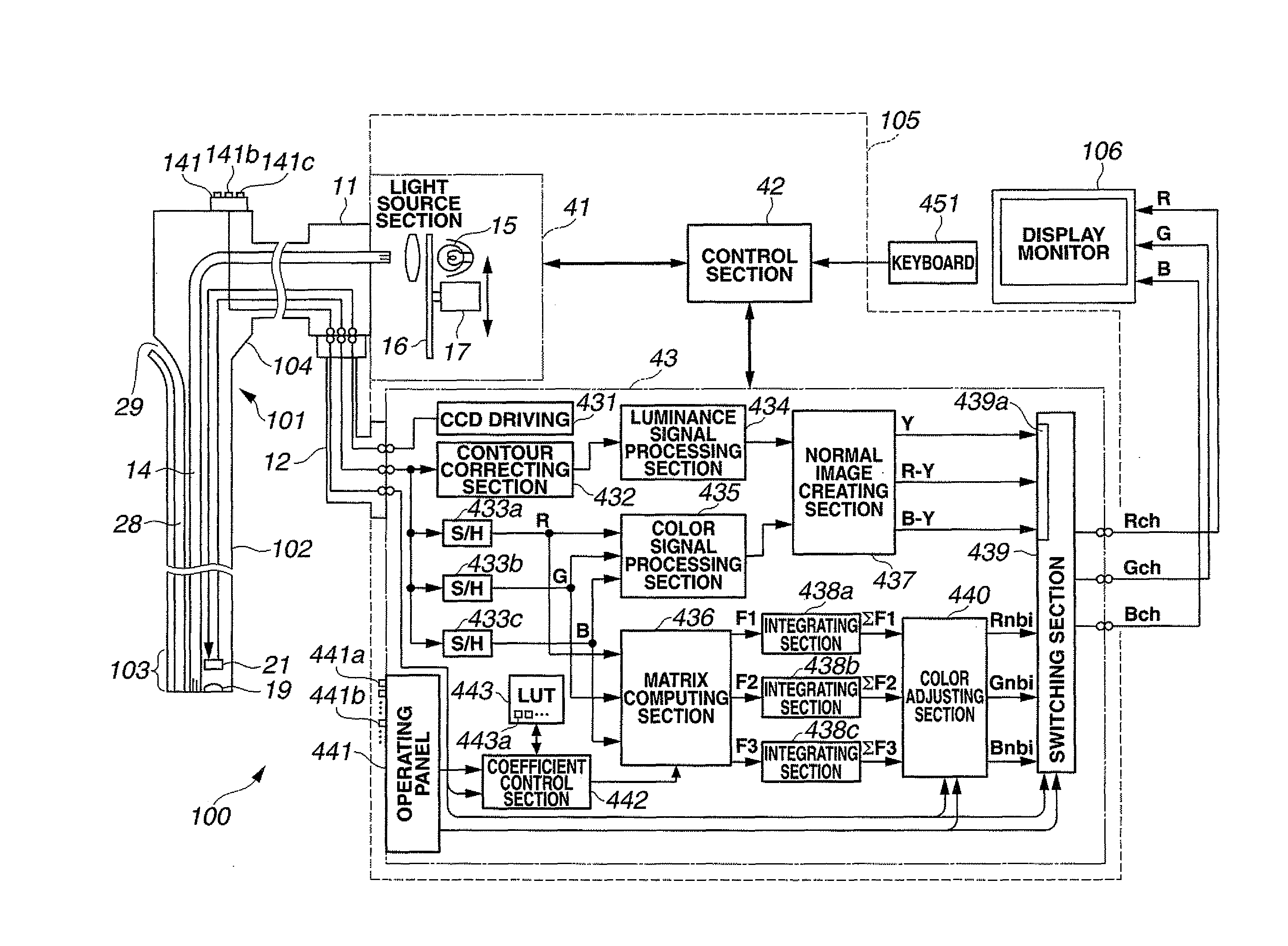
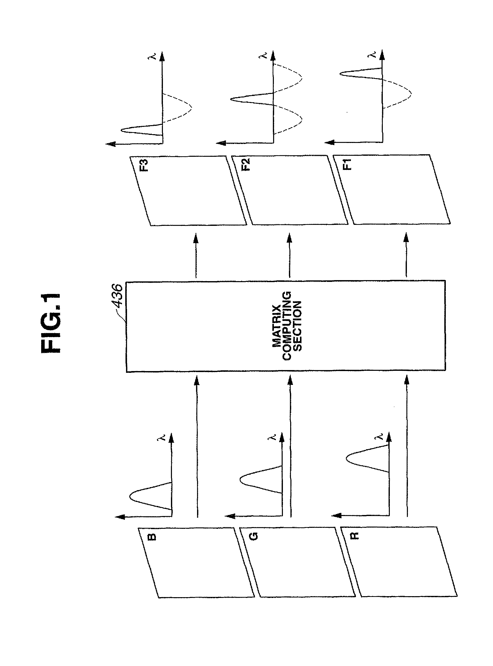
[0083]An electronic endoscope apparatus as a biological observation apparatus according to the first embodiment of the present invention irradiates illumination light from an illuminating light source to a living body that is a subject to be examined, receives light reflected off the living body based on the illumination light at a solid state image pickup device that is an image pickup section and creates a broadband color image signal from a photoelectrically converted image pickup signal, and creates from the color image signal through signal processing a spectral image signal corresponding to an image signal having a narrowband optical wavelength.

[0084]Before presenting a description on the first embodiment of the present invention, a matrix calculating method that forms the foundation of the present invention will be described below. In this case, “matrix” refers to a predete...

second embodiment

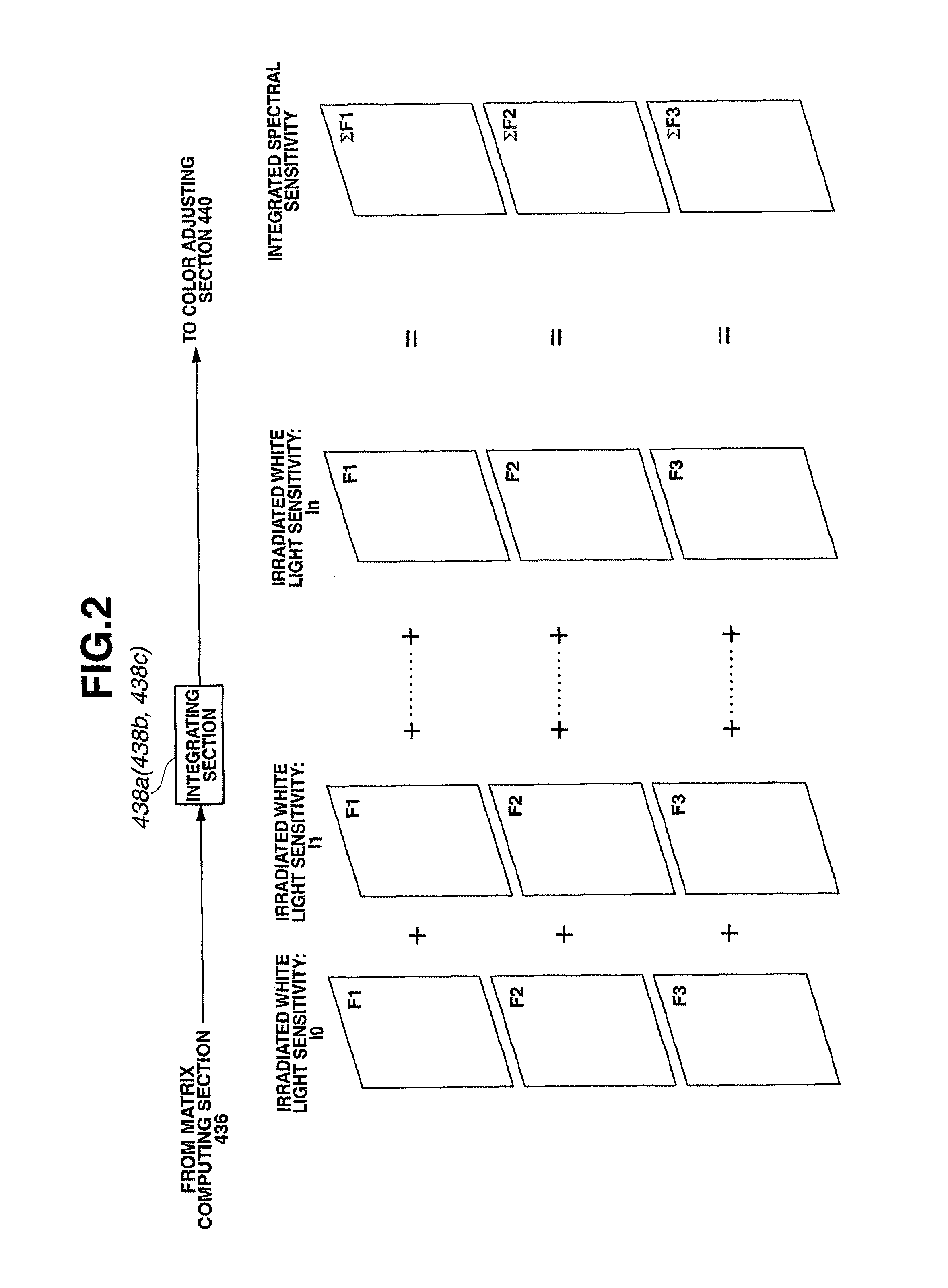
[0322]Next, the second embodiment of the present invention will be described with reference to FIG. 35. FIG. 35 shows a configuration of a peripheral portion of a color adjusting section in an electronic endoscope apparatus according to the second embodiment. The present embodiment is an illustrative example in which color adjustment by the color adjusting section 440 is suitably performed using, for example, two spectral image signals ΣF2 and ΣF3 in the configuration shown in FIG. 4 of the first embodiment. Therefore, in the present embodiment, the integrating section 438a shown in FIG. 4 has not been provided, a spectral channel image signal to be color-displayed on the display monitor 5 is created from the two spectral image signals ΣF2 and ΣF3.

[0323]In the present embodiment, as an illustrative example of a method for appropriately switching the computation coefficient of the color adjustment means, color-display of a spectral image is performed using two spectral image signals ...

third embodiment

[0339]Next, a third embodiment of the present invention will be described with reference to FIGS. 37 to 40.

[0340]The present embodiment is arranged so that, when a preset condition is met during spectral image observation mode in which a spectral image is observed, control is performed so that a forced switchover to normal image observation mode is made. More specifically, when the brightness of a spectral image reaches or falls under a threshold set in order to discriminate dark images in advance, the control section 42 switches the switching section 439 to perform control for switching to normal image observation mode.

[0341]An electronic endoscope apparatus 100 shown in FIG. 37 according to the third embodiment is the electronic endoscope apparatus 100 shown in FIG. 4, configured so that, for example, spectral image signals F1, F2 and F3 outputted from the matrix computing section 436 are inputted to a brightness judging section 171, and a signal of a comparison result (judgment r...


PUM


Abstract

A biological observation apparatus comprises a color image signal creating section that performs signal processing on either a first image pickup signal for which a subject to be examined illuminated by white illumination light is picked up by a color filter having a transmitting characteristic of a plurality of broadband wavelengths or a second image pickup signal for which a subject to be examined is picked up under illumination of frame sequential illumination lights which cover a visible range, and creates a color image signal. The biological observation apparatus comprises a spectral image signal creating section that creates a spectral image signal corresponding to a narrowband image signal through signal processing on a color image signal based on the first or second image pickup signal. The biological observation apparatus comprises one of a characteristic changing / setting section for a display color converting section that performs conversion of display colors when causing the spectral image signal to be displayed or the like, an interface section for performing an instruction operation for switching and / or confirming information including an image to be displayed, or the like.

Description

TECHNICAL FIELD[0001]The present invention relates to a biological observation apparatus that creates a spectral image signal corresponding to a quasi-narrowband filter through signal processing using a color image signal obtained by picking up an image of a living body, and displays the spectral image signal as a spectral image on a monitor.BACKGROUND ART[0002]Conventionally, an endoscope apparatus that irradiates illumination light to obtain an endoscopic image inside a body cavity is widely used as a biological observation apparatus. An endoscope apparatus of this type uses an electronic endoscope having image pickup means that guides illumination light from a light source into a body cavity using a light guide or the like and which picks up a subject image from returning light thereof, and is arranged so that signal processing of an image pickup signal from the image pickup means is performed by a video processor in order to display an endoscopic image on an observation monitor ...

Claims


Application Information

Patent Timeline
Patent Type & Authority Patents(United States)
IPC IPC(8): A61B6/00
CPCA61B1/00009A61B1/00186A61B1/045A61B1/0638A61B1/0646A61B5/0075A61B5/0084G01J3/32G01J3/50G01N21/255G01N21/31G02B23/24A61B1/063G01J3/501G01J3/513G01J2003/1213G01J2003/1221H04N2005/2255A61B1/000094A61B1/044A61B1/0655H04N23/555G01N21/27A61B5/7203
Inventor GONO, KAZUHIROAMANO, SHOICHITAKAHASHI, TOMOYAOHSHIMA, MUTSUMI
Owner OLYMPUS CORP
Learn More