Voltage detecting apparatus with voltage controlled oscillator and battery state control system

a voltage control and battery technology, applied in the direction of electric vehicles, propulsion parts, engine-driven generators, etc., can solve the problems of increasing processing load, reducing reliability, and difficulty in achieving greater voltage detecting speeds of tad converters, so as to facilitate battery-pack longevity, high resolution, and high accuracy

Active Publication Date: 2012-11-06
DENSO CORP
View PDF7 Cites 17 Cited by
  • Summary
  • Abstract
  • Description
  • Claims
  • Application Information

AI Technical Summary

Benefits of technology

[0008]For meeting demand for miniaturization, lithium ion secondary cells have been prepared to be applied as each battery cell of each of the battery modules of vehicle battery packs. Note that overcharge and / or over-discharge of lithium ion secondary cells may easily decrease the reliability of them. This therefore requires monitoring, at short intervals, whether overcharge and / or over-discharge of each lithium ion secondary cell occurs; this also requires greater voltage detecting process speeds for TAD converters.
[0009]However, response to the higher-resolution requirement for TAD converters may increase processing load required to carry out voltage detecting processes, making it difficult to achieve greater voltage detecting speeds of TAD converters.
[0012]In view of the circumstances set force above, an object of a aspect of the present invention is to provide voltage detecting apparatuses each with a voltage controlled oscillator; these voltage detecting apparatuses are improved to achieve both higher resolution and greater speeds of their voltage detecting processes.

Problems solved by technology

Note that overcharge and / or over-discharge of lithium ion secondary cells may easily decrease the reliability of them.
However, response to the higher-resolution requirement for TAD converters may increase processing load required to carry out voltage detecting processes, making it difficult to achieve greater voltage detecting speeds of TAD converters.

Method used


Image

  • Voltage detecting apparatus with voltage controlled oscillator and battery state control system
  • Voltage detecting apparatus with voltage controlled oscillator and battery state control system
  • Voltage detecting apparatus with voltage controlled oscillator and battery state control system

Examples


first embodiment

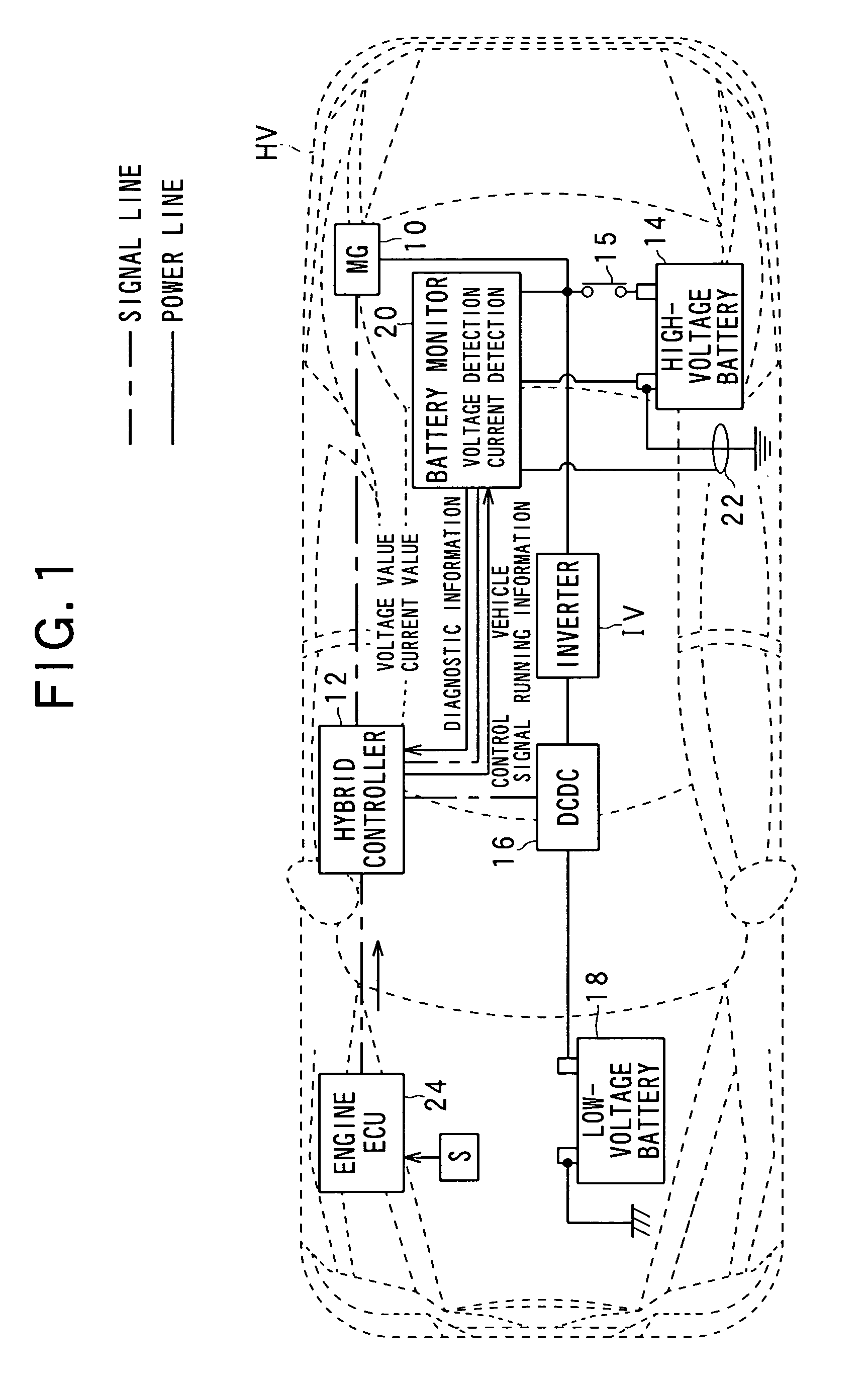
[0061]Referring to the drawings, in which like reference characters refer to like parts in several views, there is illustrated in FIG. 1 an example of the overall structure of an electrical vehicle control system installed in a hybrid vehicle HV according to the first embodiment.

[0062]The vehicle control system includes a motor-generator, referred to simply as “MG”, 10, a hybrid controller 12, a high-voltage battery 14, a main relay 15, a DC to DC converter 16, an inverter IV, a low-voltage battery 18, a battery monitor system 20, a current sensor 22, and an internal combustion engine control unit (engine ECU) 24.

[0063]Referring to FIG. 1, the MG 10, the hybrid controller 12, the high-voltage battery 14, the main relay 15, the DC to DC converter 16, the inverter IV, the battery monitor system 20, the current sensor 22, and the engine ECU 24 can send and receive signals thereamong via signal lines. Similarly, the MG 10, the high-voltage batter 14, the DC-DC converter 16, the inerter ...

second embodiment

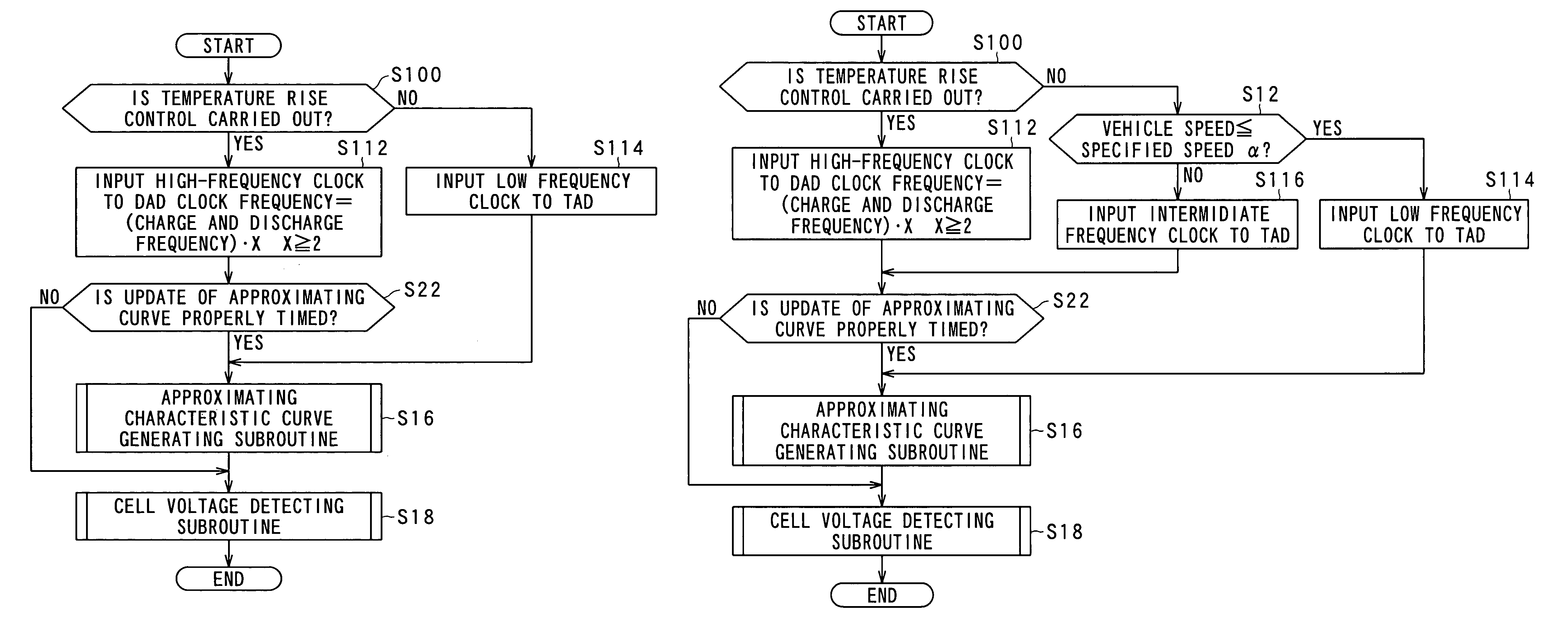
[0194]A battery monitor according to the second embodiment of the present invention will be described hereinafter with reference to FIG. 13.

[0195]The structure of the battery monitor according to the second embodiment is substantially identical to that of the battery monitor according to the first embodiment except for the following different points. So, like parts between the battery monitors according to the first and second embodiments, to which like reference characters are assigned, are omitted or simplified in description.

[0196]A voltage detecting routine to be executed by the battery monitor 20 according to the second embodiment will be described hereinafter. The voltage detecting routine is designed to be repeatedly executed by the batter monitor 20 at a preset cycle in accordance with a voltage detecting program stored in the battery monitor 20.

[0197]Like operations between the voltage detecting routines illustrated in FIGS. 10 and 13, to which like reference characters are...

third embodiment

[0206]A battery monitor according to the third embodiment of the present invention will be described hereinafter with reference to FIGS. 14 and 15.

[0207]The structure of the battery monitor according to the third embodiment is substantially identical to that of the battery monitor according to the first embodiment except for the following different points. So, like parts between the battery monitors according to the first and third embodiments, to which like reference characters are assigned, are omitted or simplified in description.

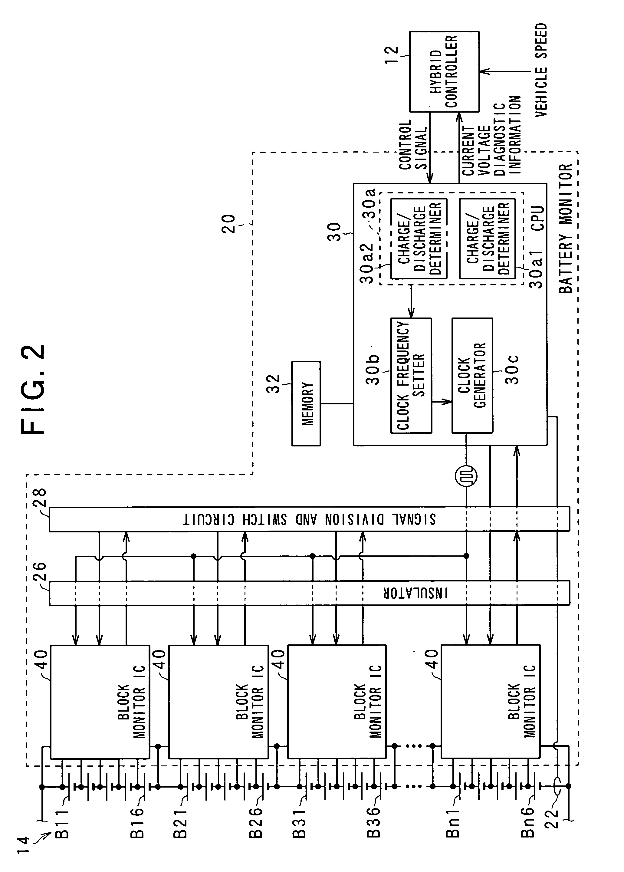
[0208]The resolution determiner 30a consists of a charge / discharge determiner 30a2 in place of or in addition to the running state determiner 30a1.

[0209]A voltage detecting routine to be executed by the battery monitor 20 according to the third embodiment will be described hereinafter. The voltage detecting routine is designed to be repeatedly executed by the batter monitor 20 at a preset cycle in accordance with a voltage detecting program stored in the...


PUM

PropertyMeasurementUnit
currentsaaaaaaaaaa
voltageaaaaaaaaaa
voltageaaaaaaaaaa

Abstract

In a voltage detecting apparatus, a voltage controlled oscillator, when an input voltage is applied thereto, outputs a signal with a logical value that is periodically inverted. A detector counts a number of logical inversion of the output signal from the voltage controlled oscillator over an interval between edges of pulses of a pulse signal to thereby generate, based on the counted number of logical inversion, digital data as a detected result of the input voltage. A determiner determines whether a reduction of a time required to detect the input voltage is higher in priority than an increase of a resolution of detection of the input voltage. A variably setting unit variably sets a frequency of the pulse signal based on a result of the determination of whether the reduction of the time required to detect the input voltage is higher in priority than the increase of the resolution of detection of the input voltage.

Description

CROSS REFERENCE TO RELATED APPLICATIONS[0001]This application is based on Japanese Patent Applications 2008-98453 and 2009-043314 filed on Apr. 4, 2008 and Feb. 26, 2009, respectively. This application claims the benefit of priority from the Japanese Patent Application, so that the descriptions of which are all incorporated herein by reference.FIELD OF THE INVENTION[0002]The present invention relates to voltage detecting apparatuses provided with a voltage controlled oscillator and a digital-data output circuit, and battery state control systems provided with such a voltage detecting apparatus. More particularly, the voltage controlled oscillator works to output a signal with a logical value that is periodically inverted when an input voltage is applied thereto. The digital-data generating circuit works to count the number of logical inversion of the output signal from the voltage controlled oscillator over an interval between edges of pulses of a pulse signal, such as a clock to th...

Claims


Application Information

Patent Timeline
Patent Type & Authority Patents(United States)
IPC IPC(8): H02J7/04H02J7/16G01N27/416B60L50/16
CPCB60K6/48B60L11/187B60L11/1875B60W10/26G01R19/0084G01R31/3658H01M10/443H01M10/48B60W20/00B60W2510/246Y02T10/705Y02T10/6221Y02T10/7005B60W2520/10G01R31/396B60L58/24B60L58/27Y02T10/62Y02T10/70Y02E60/10B60W2510/244B60W2050/0006B60W20/13
Inventor YAMAMOTO, HIROYOSHITAMURA, HIROSHI
Owner DENSO CORP
Why Eureka
Try Eureka