System and method to form and heat-treat a metal part

a metal part and heat treatment technology, applied in the field of titanium and other metal parts, can solve the problems of warping, distortion, cracking, stress within the metal part, and adds to the overall time and cost of manufacturing the metal part using eb

Active Publication Date: 2012-11-13
SPIRIT AEROSYSTEMS
View PDF4 Cites 23 Cited by
  • Summary
  • Abstract
  • Description
  • Claims
  • Application Information

AI Technical Summary

Benefits of technology

[0007]The present invention provides a system and method for direct manufacturing of a metal part, such as a titanium part, without removing the metal part from an airtight chamber for intermediate stress-relief. Specifically, the system and method may allow the metal part to be heat-treated at an intermediate point during the manufacturing process within the chamber by selectively applying stress-relieving joule heat to the metal part.
[0009]The wire feeder and the EB source may deposit metal melted from the metal wire onto the metal plate to build up a particular metal part having desired shapes and dimensions. The EB source may be used during manufacture of the metal part to melt the metal wire, bonding it to the metal plate and / or preceding layers of the metal wire. The current-providing apparatus may comprise at least one bus bar and an electrical power unit and may provide electrical current to the metal plate while the wire feeder is not depositing metal wire onto the metal plate, thereby heat-treating the metal part. Additionally, the EB source may also be used to heat select portions of the metal part to a stress-relieving temperature below the melting point of that particular metal, thereby assisting the current-providing apparatus in providing even heat to the metal part.

Problems solved by technology

Because of the difference in temperatures of the metal plate and the metal wire heated by electron beam, stress may form within the metal part, such as warping, distortion, cracking, and other stresses introduced to the part during deposition of the metal wire.
The shipping of the part and the use of separate heat treating equipment at a second facility adds to the overall time and cost of manufacturing the metal part using EB direct manufacturing.

Method used


Image

  • System and method to form and heat-treat a metal part
  • System and method to form and heat-treat a metal part
  • System and method to form and heat-treat a metal part

Examples


Embodiment Construction

[0018]The following detailed description of the invention references the accompanying drawings that illustrate specific embodiments in which the invention can be practiced. The embodiments are intended to describe aspects of the invention in sufficient detail to enable those skilled in the art to practice the invention. Other embodiments can be utilized and changes can be made without departing from the scope of the present invention. The following detailed description is, therefore, not to be taken in a limiting sense. The scope of the present invention is defined only by the appended claims, along with the full scope of equivalents to which such claims are entitled.

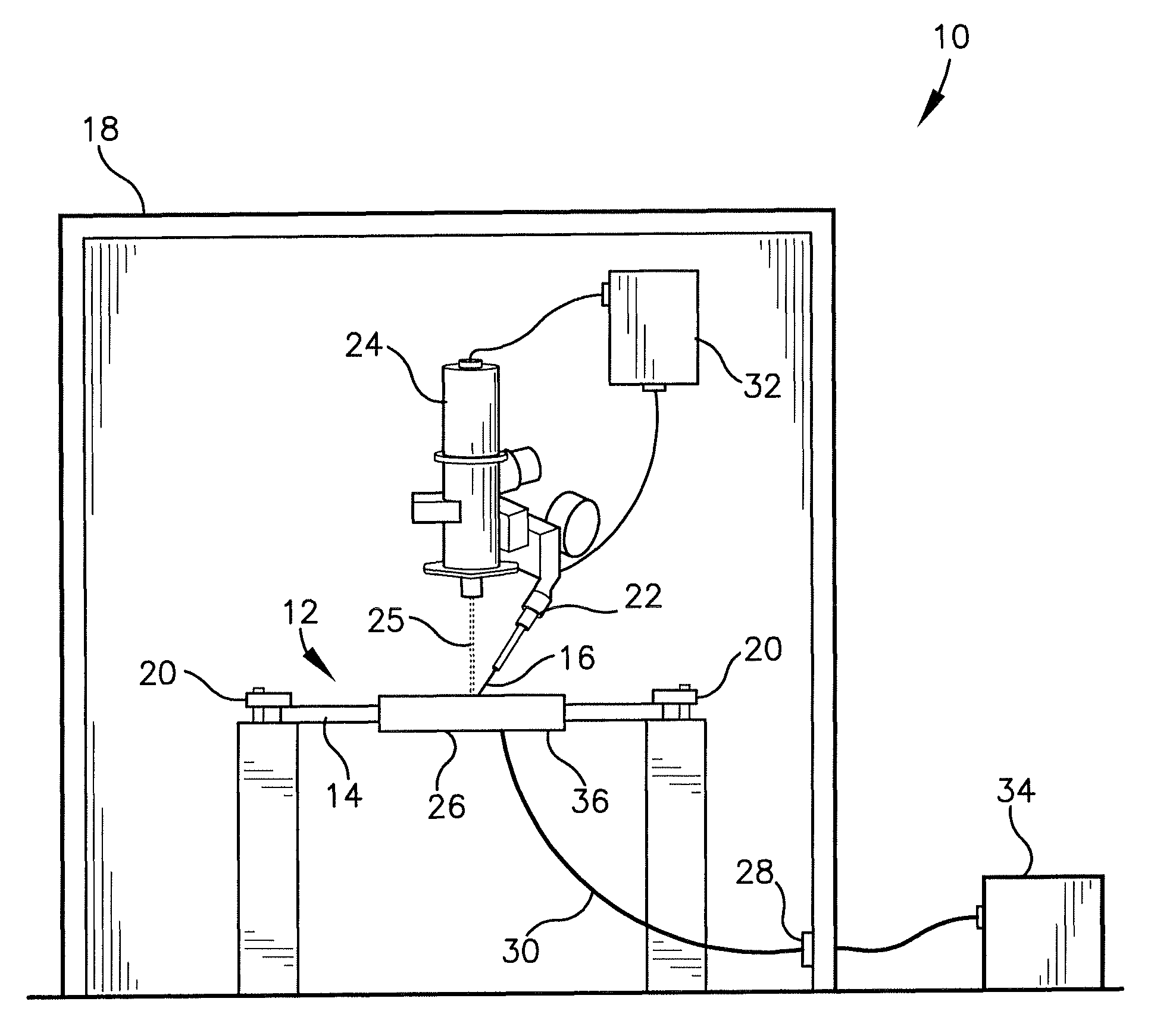
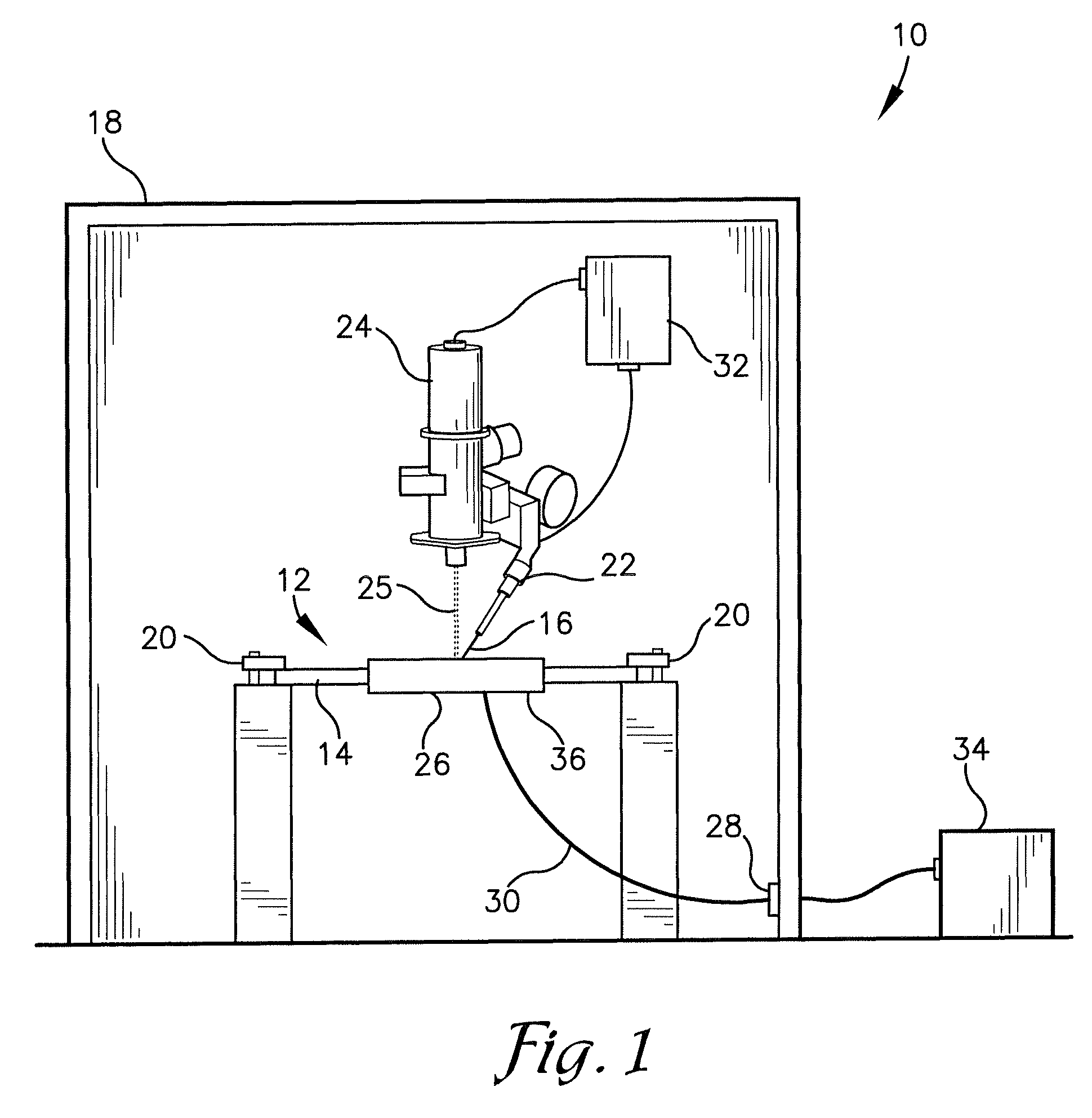
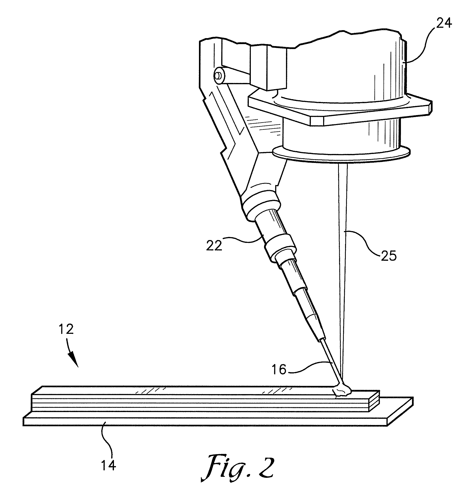
[0019]FIG. 1 illustrates a system 10 for forming and stress relieving a metal part 12 comprising a metal plate 14 and metal wire 16. The metal plate 14 and the metal wire 16 may be composed of the same type of metal, which may be any type of metal, such as titanium, titanium alloys such as Ti-6Al-4V, aluminum and nickel...


PUM

PropertyMeasurementUnit
electric currentaaaaaaaaaa
electrical currentaaaaaaaaaa
temperatureaaaaaaaaaa

Abstract

A system and method for direct manufacturing and stress relieving a metal part without removing the metal part from a vacuumed chamber. The system may comprise the chamber, a wire feeder for depositing a metal wire onto a metal plate, an electron beam (EB) source for providing an electron beam to melt the metal wire during deposition, and a current-providing apparatus for joule heating the metal plate to provide heat treatment to the metal part. The method may comprise depositing the metal wire onto the metal plate within the vacuumed chamber, then providing intermediate stress relief after a portion of the metal wire is deposited onto the metal plate by applying an electrical current to the metal part. The electron beam may also be set at a temperature below a melting point of a particular metal of the metal part for relieving stress in the metal part.

Description

BACKGROUND[0001]1. Field[0002]The present invention relates to titanium and other metal parts. More particularly, the invention relates to a system and method for direct manufacturing of and providing stress relief to metal parts for aircrafts and other applications.[0003]2. Related Art[0004]Electron beam (EB) direct manufacturing is a process for making titanium parts and other metal parts for aircrafts and other applications. In EB direct manufacturing, a metal wire is deposited onto a metal plate and an electron beam bombards the wire as it is deposited onto the metal plate within a vacuumed chamber. The electron beam provides a focused heat to the metal wire for melting and deposition of the metal wire, bonding the metal wire to the metal plate and preceding metal wire layers. The electron beam transfers heat to the metal wire via conduction and / or radiation. Direct manufacturing is sometimes alternatively referred to as additive manufacturing, metal rapid prototyping, electron ...

Claims


Application Information

Patent Timeline
Patent Type & Authority Patents(United States)
IPC IPC(8): C21D1/04
CPCC22F1/183C23C4/124C23C4/128C23C4/129C23C4/137B33Y70/00B33Y10/00
Inventor WOODS, BRYAN DAVIDNASSERRAFI, RAHBAREHLERS, HELEN
Owner SPIRIT AEROSYSTEMS
Why Eureka
Try Eureka