In vivo gene sensors

a gene sensor and in vivo technology, applied in the field of in vivo gene sensor, can solve the problems of not keeping up with the evolution of antibiotic resistance, the cost and cost of cycling antibiotics, and the inability to control the resistance of resistant organisms, so as to achieve the effect of suppressing the expression of the effect gen

Active Publication Date: 2012-12-11
TRUSTEES OF BOSTON UNIV +1
View PDF10 Cites 22 Cited by
  • Summary
  • Abstract
  • Description
  • Claims
  • Application Information

AI Technical Summary

Problems solved by technology

Though the advent of antibiotics has reduced the impact of bacterial diseases on human health, the constant evolution of antibiotic resistance poses a serious challenge to the usefulness of currently available antibiotic drugs3-7.
However, the introduction of new agents to the market by pharmaceutical companies has not kept pace with the evolution of antibiotic resistance1,3.
Surveillance and containment measures have been instituted in government and hospitals so that problematic infections are rapidly detected and isolated but do not address the fundamental evolution of resistance12.
Cycling antibiotics is one method of controlling resistant organisms but is costly and may not be efficacious27, 28.
Bacterial biofilms are sources of contamination that are difficult to eliminate in a variety of industrial, environmental and clinical settings.
Bacterial biofilms are associated with many human and animal health and environmental problems.
Biofilms also contaminate surfaces such as water pipes and the like, and also render other industrial surfaces hard to disinfect97.
Their use is often severely compromised as a result of bacterial biofilm infection which is associated with significant mortality and increased costs.
Treatment of CVC-associated infections with conventional antimicrobial agents alone is frequently unsuccessful due to the extremely high tolerance of biofilms to these agents.
This is a costly and risky procedure and re-infection can quickly occur upon replacement of the catheter.

Method used


Image

  • In vivo gene sensors
  • In vivo gene sensors
  • In vivo gene sensors

Examples


example 1

A Bacterial Gene Sensor Circuit

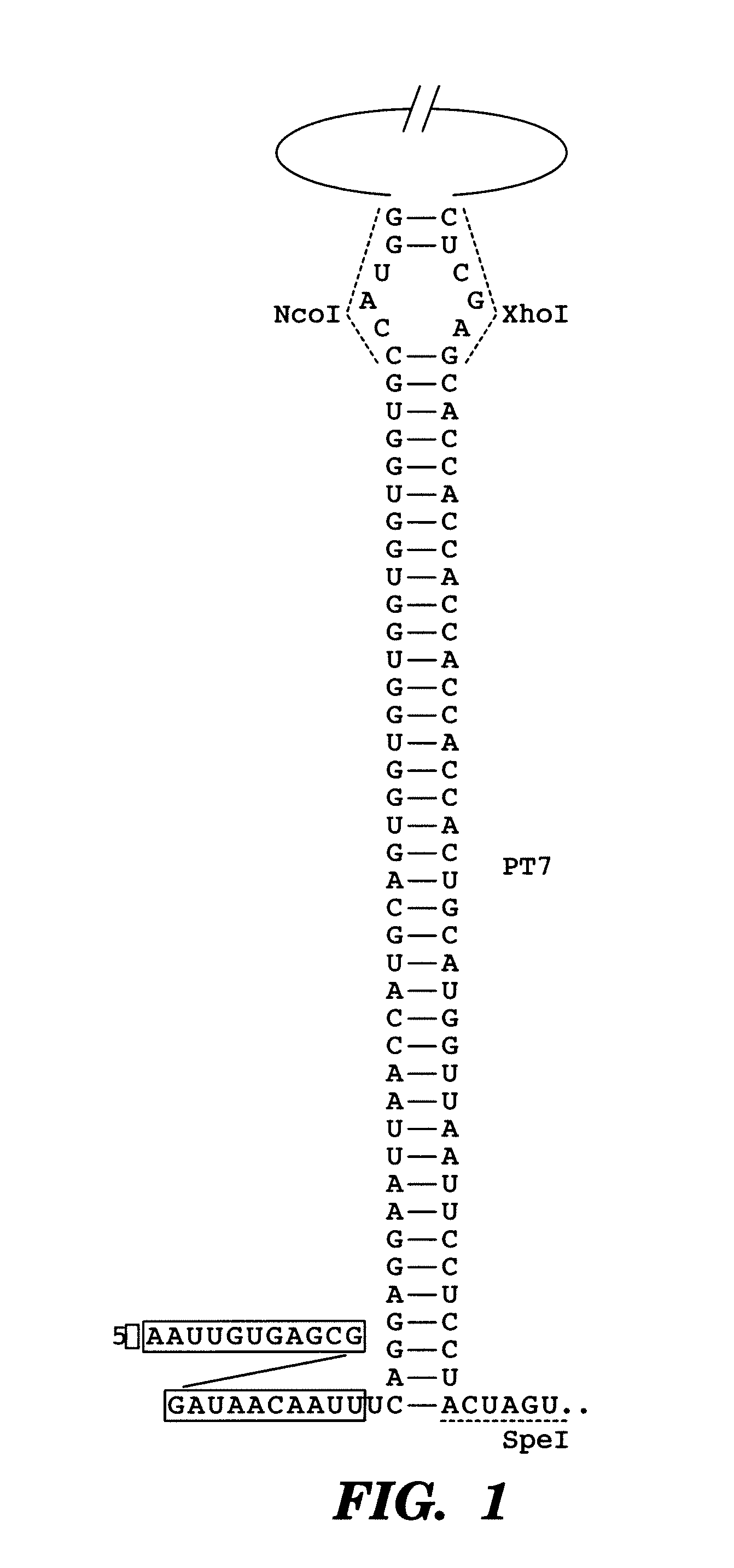
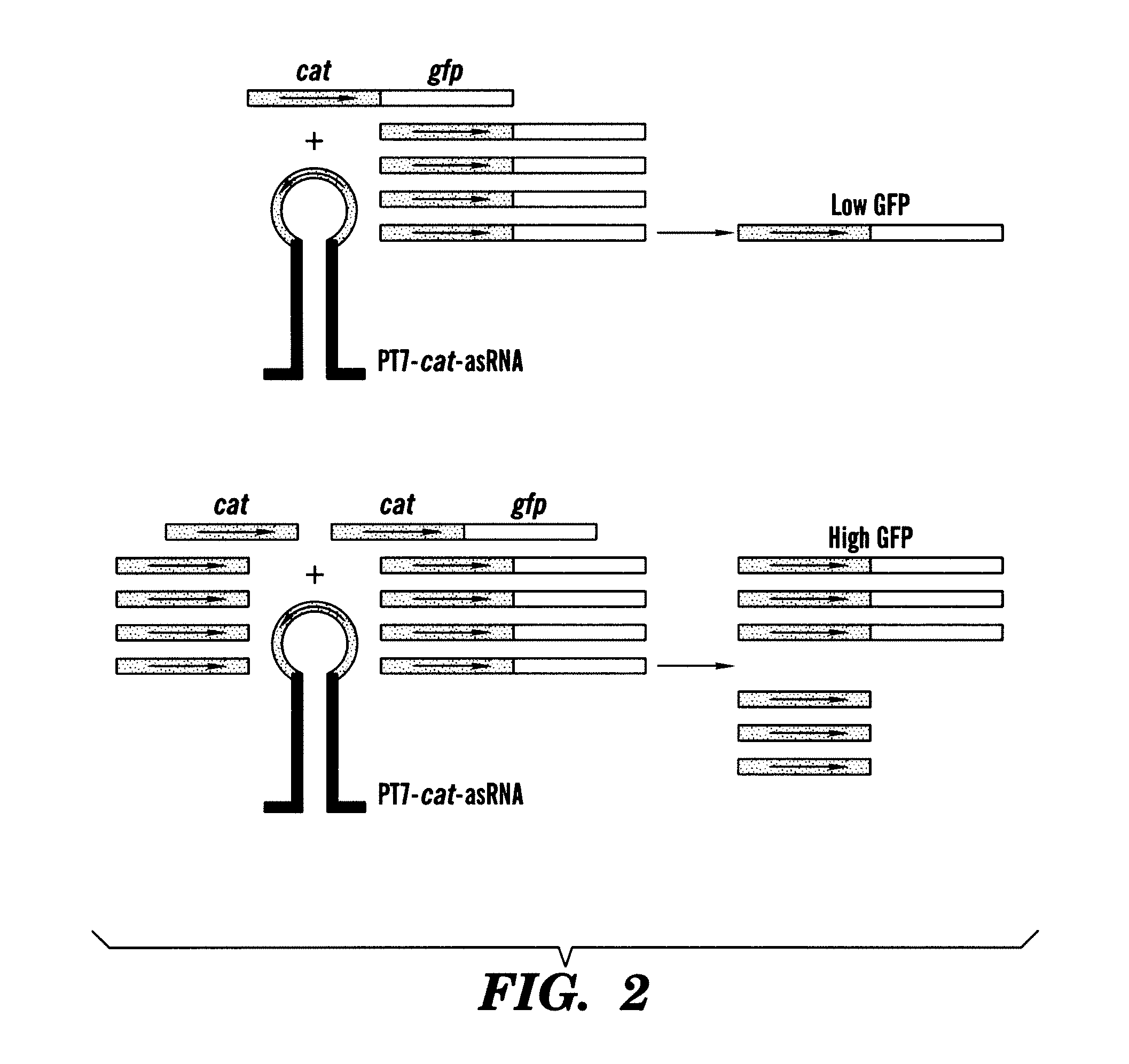
[0184]As a first demonstration of the gene sensor circuit, described herein, an inhibitory nucleic acid construct was designed to express an antisense RNA target; the antisense resistance gene CAT. This was coupled with a sensor-effector construct with a portion of the CAT gene fused to GFP (odi) sequences. The read-out is GFP fluorescence.

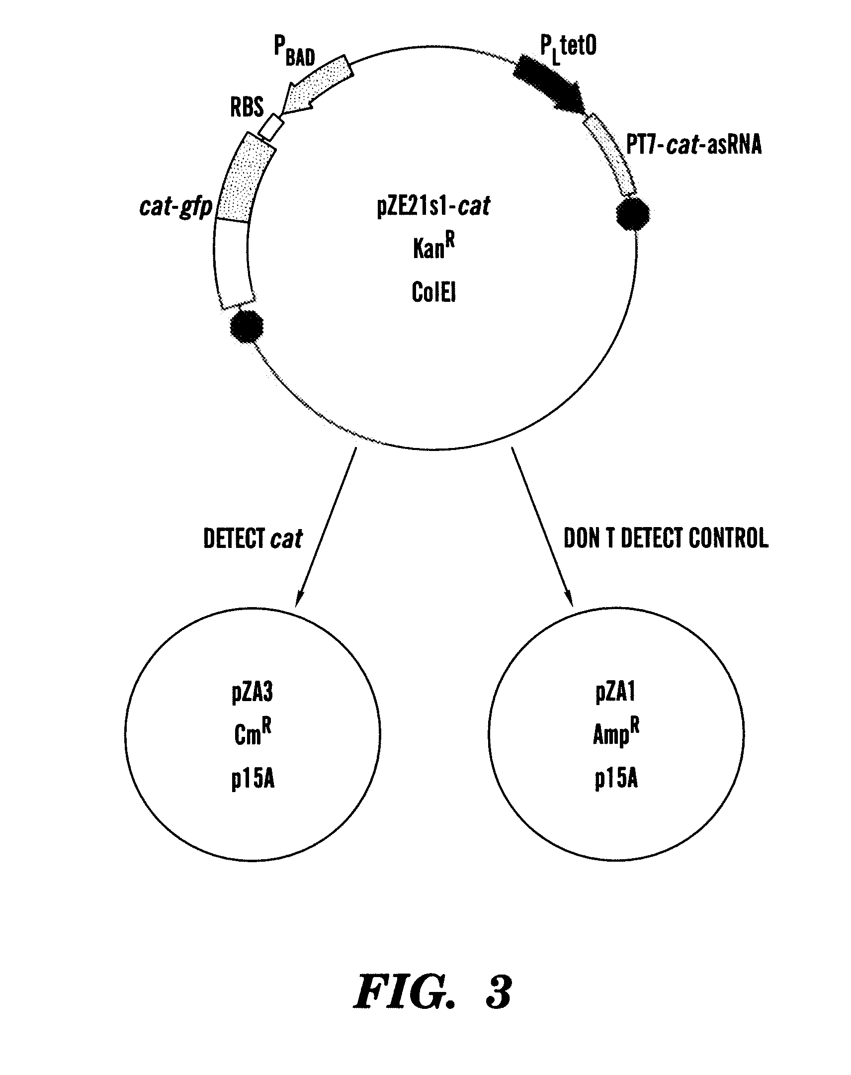
[0185]In one example, the paired-termini (PT7) design described by Nakashima et al, 200646 is extended to produce an antisense RNA similar to that shown in FIG. 1. The PT7 construct produces an antisense RNA with longer half-lives in vivo, allowing for greater antisense effect46. Starting with the PT7 construct shown in FIG. 1, the NcoI and XhoI restriction enzyme sites were replaced by HindIII and NheI sites, respectively. In this example, the target gene encodes for chloramphenicol resistance and is denoted as cat. This target gene represents a very well-characterized and important gene in E. coli encoding chloramp...

example 2

[0186]In a second example, an RNA sensor design utilizes the pTAK series of plasmids described by Gardner et al, 200047. Instead of cloning the antisense RNA for the target RNA into the upstream region of lacI, the PT7-cat-asRNA construct is placed downstream of the lacI gene to create pTAKs3-cat as depicted in FIG. 6. This design is utilized for target genes where the primary mode of the PT7 construct's antisense RNA action is through RNA degradation, as this system relies on lacI-PT7-cat-asRNA binding to cat mRNA to trigger degradation of the lacI-PT7-cat-asRNA RNA46. Reduction of the levels of the Lac repressor increase GFP output. The RNA sensor design shown in FIG. 5 is realized by cloning PT7-asRNA fragments into the AscI site in pTAK132 from Gardner et al, 200047. The cI857 gene in pTAK132 is removed by restriction digest in order to obtain a continuous output behavior rather than discontinuous switch behaviour. This permits the effector molecule to be in two main states: on ...

example 3

[0187]The following example demonstrates how to determine the sensitivity and false positive rate of the gene sensor described herein. Generally, a higher false positive rate is preferred, i.e., greater sensitivity, at the potential expense of some false positives, as opposed to a higher false negative rate, in which positive cells are not detected.

Definitions

[0188]True Positive (TP)—cell has target gene and is sensed[0189]False Negative (FN)—cell has target gene but is not sensed[0190]True Negative (TN)—cell doesn't have target gene and is not sensed[0191]False Positive (FP)—cell doesn't have target gene but is sensed

[0192]Using standard statistical terms, let us define selective sensing as a low false-positive rate (meaning that a low number of cells that do not have the target are sensed or killed=FP / (TN+FP))

[0193]Still want respectable sensitivity (meaning that a good number of cells that do have the target are actually sensed=TP / (TP+FN))

[0194]FIG. 6 shows the sensitivity and fa...


PUM

PropertyMeasurementUnit
drug resistanceaaaaaaaaaa
multi-drug resistanceaaaaaaaaaa
resistanceaaaaaaaaaa

Abstract

Described are methods and compositions for the detection of target genes. The inventors have developed a synthetic nucleic acid sensor-effector gene circuit. In cells without a target gene, the circuit suppresses e.g., effector production, but in the presence of the target gene the suppression is subject to competition, such that the synthetic sensor is de-repressed and permits expression of the effector gene. The methods and compositions described further permit the selective expression of an effector gene in those cells expressing the target gene. In this manner, cells expressing a target gene can be selectively targeted for treatment or elimination. In certain aspects, the methods and compositions described permit the selective expression of an agent such as a therapeutic gene product, in a specifically targeted population of cells in an organism.

Description

CROSS REFERENCE TO RELATED APPLICATIONS[0001]This application is a 35 U.S.C. §371 National Phase Entry application of International Application No. PCT / US2009 / 034296, filed on Feb. 17, 2009, which designates the United States, and which claims the benefit of priority under 35 U.S.C. §119(e) of U.S. Provisional Application No. 61 / 029,158 filed on Feb. 15, 2008, the contents of which are incorporated herein by reference in their entirety.GOVERNMENT SUPPORT[0002]This invention was made with Government Support under Contract No. EF-0425719 awarded by the National Science Foundation. The Government has certain rights in the invention.FIELD OF THE INVENTION[0003]The present invention relates to the detection of cells expressing a target gene.BACKGROUND OF THE INVENTION[0004]Bacteria rapidly develop resistance to antibiotic drugs within years of their introduction to the clinic1. Antibiotic resistance can be acquired by horizontal gene transfer or can result from persistence, in which a sm...

Claims


Application Information

Patent Timeline
Patent Type & Authority Patents(United States)
IPC IPC(8): C07H21/04
CPCC12N15/1086C12N15/111C12N15/63C12N2320/50C12N2310/111
Inventor COLLINS, JAMES J.LU, TIMOTHY KUAN-TA
Owner TRUSTEES OF BOSTON UNIV
Why Eureka
Try Eureka