Low voltage detector

a detector circuit and low voltage technology, applied in the field of low voltage detector circuits, can solve the problems of mcu consuming maximum power, high power lvd, and consuming an undesired large amount of power,

Inactive Publication Date: 2012-12-11
NXP USA INC
View PDF11 Cites 13 Cited by
  • Summary
  • Abstract
  • Description
  • Claims
  • Application Information

AI Technical Summary

Problems solved by technology

However, such an LVD (hereinafter “high power LVD”) can consume an undesirably large amount of power due to its complexity.
An MCU has a full power, or run, mode during which time many circuits are operating and, as a result, when in run mode, an MCU may consume maximum power.
Such a flag may force an asynchronous reset of an MCU as a means to prevent the MCU from entering an unpredictable (and consequently undesirable) state, or the flag may generate an interrupt to run a specific subroutine for a low voltage condition.
High power LVDs usually consume tens to hundreds of microamperes (μA) because they require voltage dividers and bandgap reference voltages to properly operate with high accuracy.
When an MCU is powered from a battery, a lower current consumption by a low power LVD results in longer battery life.
Some LVDs disadvantageously use a reference voltage that varies with the threshold voltage (VT) of a metal oxide semiconductor field effect transistor (MOSFET).
When an LVD uses a reference voltage that depends upon threshold voltage, the part-to-part variation of the LVD is disadvantageously great.
Therefore, such an LVD is either disadvantageously affected by temperature changes, or it requires additional circuitry that provides temperature compensation but which consumes additional power.

Method used


Image

  • Low voltage detector
  • Low voltage detector
  • Low voltage detector

Examples


Embodiment Construction

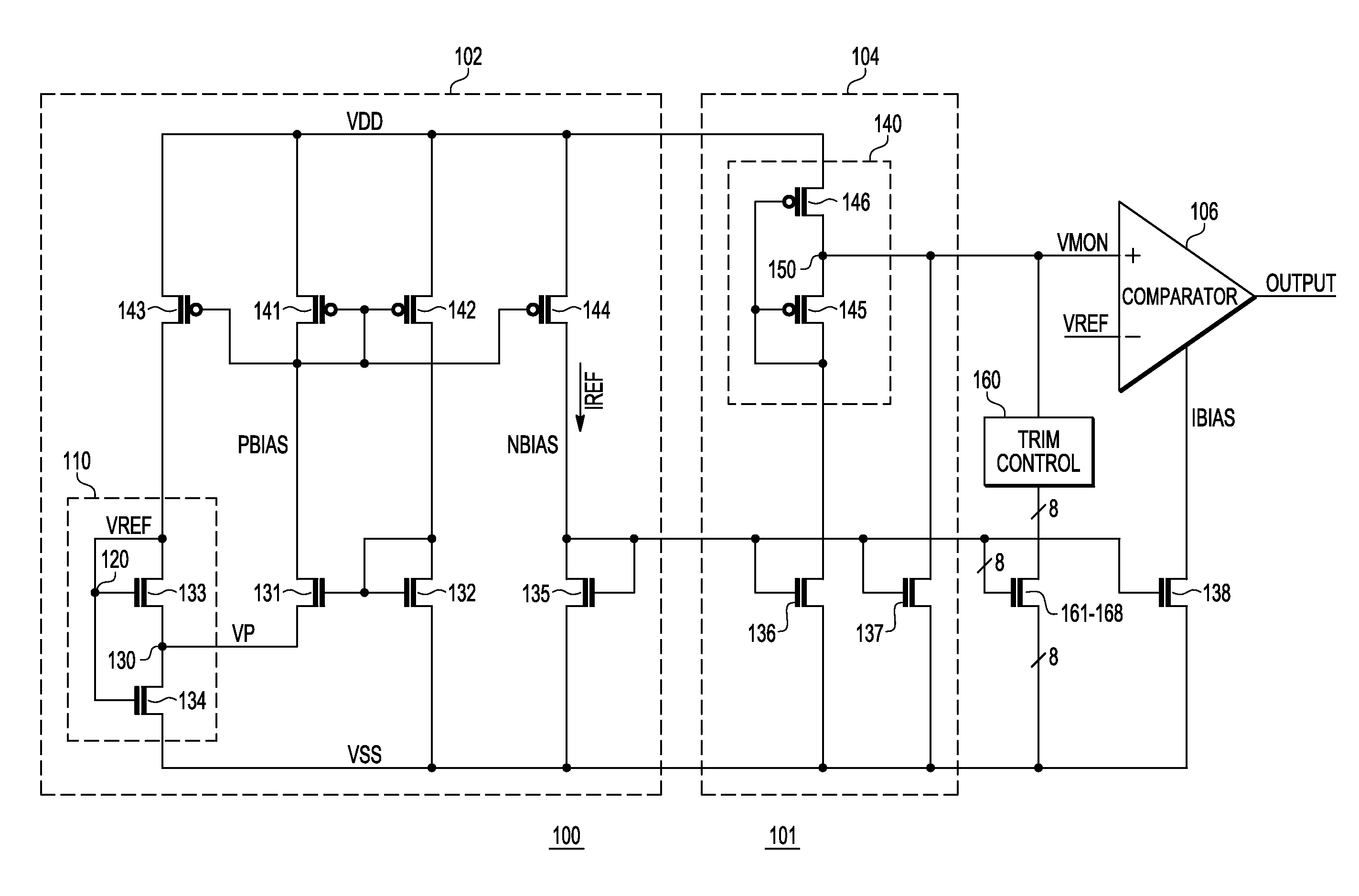
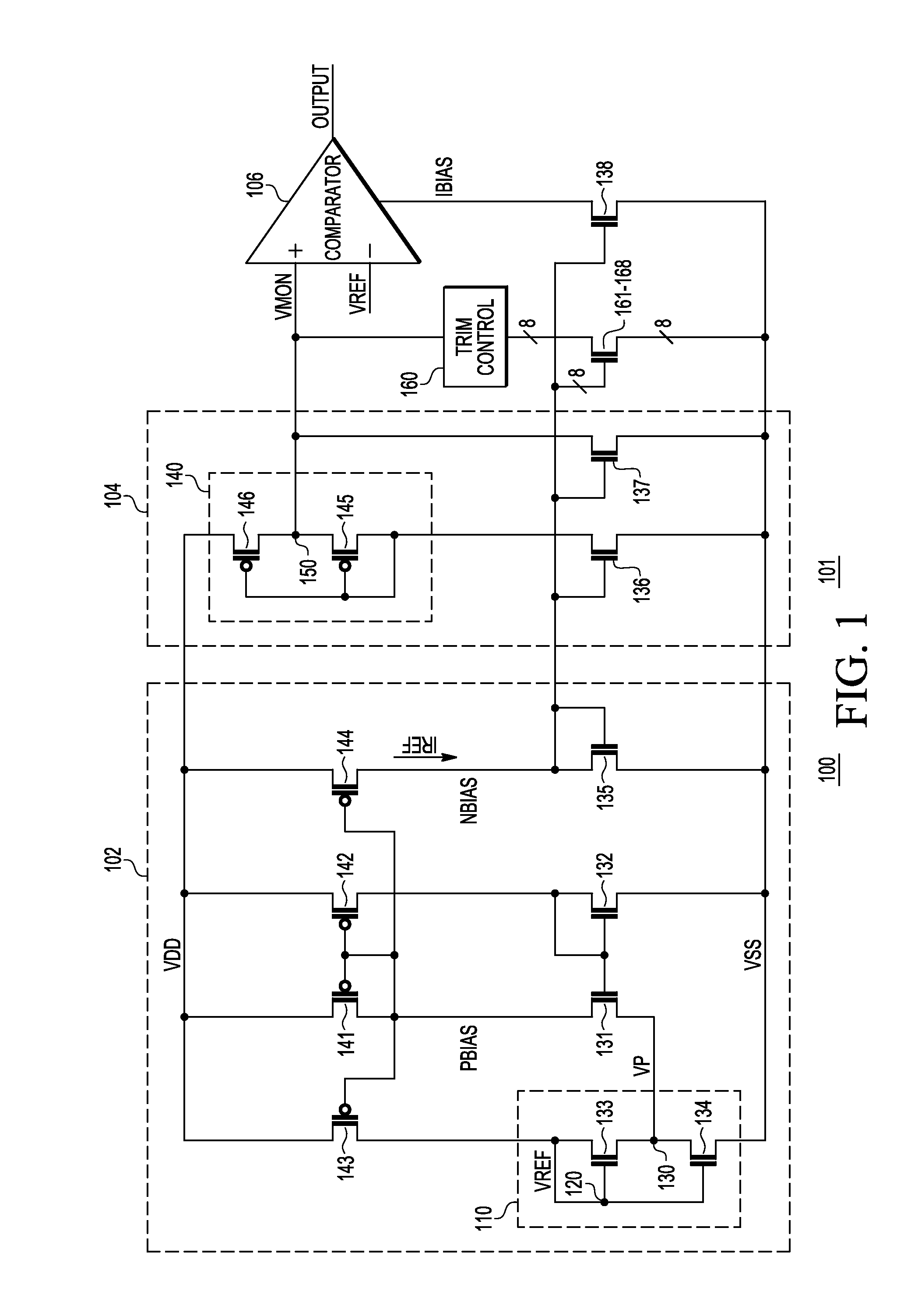
[0018]FIG. 1 is a schematic of a low power consumption, low voltage detector (LVD) 100 in accordance with one embodiment of the invention, suitable for a microcontroller unit (MCU) and other electronic applications, which delivers a safe operating state even when a minimum power supply voltage specification is violated. The invention allows implementation of a robust LVD 100 that operates with a very low quiescent current during standby mode. In one embodiment, the LVD 100 is disposed on a substrate of an integrated circuit 101. The LVD 100 monitors the power supply voltage VDD of an MCU, and provides a low voltage indication of VDD.

[0019]In one embodiment, the LVD 100 comprises a voltage and current reference circuit 102, a power supply voltage monitor circuit 104, and a low-power voltage comparator 106.

[0020]The voltage and current reference circuit 102 outputs a reference voltage VREF, which is, ideally, a fixed DC voltage that does not change with temperature or changes within a...


PUM


Abstract

A low voltage detector (100) includes a voltage and current reference circuit (102); a power supply voltage monitor circuit (104), coupled to the voltage and current reference circuit and to a power supply; and a voltage comparator (106), coupled to the voltage and current reference circuit and to the power supply voltage monitor circuit. The voltage and current reference circuit includes a self-cascode MOSFET structure (SCM) (110) that produces a reference voltage. The power supply voltage monitoring circuit includes another SCM (140) that produces a monitor voltage, related to the power supply voltage. The reference voltage and the monitor voltage have a same behavior with changes in temperature, thereby allowing the trip point of the low voltage detector to minimally vary with temperature. The low voltage detector is disposed on an integrated circuit (101), and the transistors of the low voltage detector consist of only CMOS transistors.

Description

BACKGROUND[0001]1. Field[0002]This invention relates generally to low voltage detector circuits and more specifically to a low power consumption, low voltage detector circuit disposed on an integrated circuit and fabricated using a complementary metal oxide semiconductor (CMOS) process.[0003]2. Related Art[0004]Electronic devices frequently employ a voltage detector to indicate if a particular voltage is outside a specified range. For example, battery operated devices often include a voltage detector to provide a low voltage indication when the voltage supplied by the battery decreases below a predetermined level. The low voltage indication can notify the user of the device that the battery should be replaced or recharged. In some electronic devices, it is desirable that a low voltage detector (LVD) have a relatively fine resolution, so that the LVD is able to determine when a monitored voltage is within a narrow range. However, such an LVD (hereinafter “high power LVD”) can consume...

Claims


Application Information

Patent Timeline
Patent Type & Authority Patents(United States)
IPC IPC(8): H01L35/00H03K5/22
CPCG01R19/16552G06F1/28
Inventor VILAS BOAS, ANDRE LUISOLMOS, ALFREDODE LACERDA, FABIOCAMACHO GALEANO, EDGAR MAURICIO
Owner NXP USA INC
Why Eureka
Try Eureka