Occlusion device and method of use

a technology of occlusion device and occlusion chamber, which is applied in the direction of stents, dilators, surgery, etc., can solve the problems of cell death, brain tissue ischemia, and plaque or other material parts loosening and being released, and a major risk for patients

Active Publication Date: 2012-12-18
TYCO HEALTHCARE GRP LP
View PDF80 Cites 56 Cited by
  • Summary
  • Abstract
  • Description
  • Claims
  • Application Information

AI Technical Summary

Benefits of technology

[0012]The device allows for the occlusion of two vessels, and in particular, vessels having a bifurcation area from which extends a plurality of branches or vessels. For example, the device can be used in the external carotid artery and the common carotid artery to treat a stenosis located in the internal carotid artery. In contrast to balloon catheter-based devices, occlusion can be accomplished without necessitating the usage of devices, tools, or fluids that have to remain in the catheter of the device during the intervention. Because of this, the lumen of the catheter can serve as a guide for other instruments necessary for the intervention, such as interventional tools. This results in a catheter that has a relatively small outside diameter, e.g., about 7.5 French or less.
[0035]After the removal of the elongate stretching member from the lumen of the catheter, the distal end of the guidewire will be retracted proximally until it reaches an aperture of the catheter distal to the proximal end of the proximally located self-expandable area and is advanced distally through the aperture into the other branch of the bifurcation. Thereby the guidewire will be brought into a position for guiding intervention tools such as a balloon catheter or balloon catheter. Consequently, it is not necessary to remove the guidewire completely from the catheter to introduce a different device. The exchange of the elongate stretching member and the intervention tool can be a rapid “over-the-wire” exchange. The distance over which a guidewire has to be advanced from the point of entry to the location of treatment is considerable, in particular for treatments of carotid vessels, where the devices will typically be inserted via the femoral artery. By avoiding the retraction and exchange of guidewires, the intervention time can be reduced considerably.

Problems solved by technology

There is, however, a risk with these procedures, whereby parts of the plaque or other material may loosen and be released as emboli into the blood stream.
The emboli have a high probability of becoming lodged within the cerebrovasculature causing flow blockage, brain tissue ischemia, and cell death.
This represents a major risk for the patient.
Conventional filter devices are disadvantageous in that they have to be positioned in a distal position relative to the stenosis in order to catch the released or sloughed off particles, which, according to the natural antegrade blood flow, would be transported towards the cerebral brain tissues and ultimately the brain.
Unfortunately, the process of guiding the filter through the area of the stenosis may itself result in the dislodging of particulate matter, which then may lead to emboli.
The above-noted systems are, however, disadvantageous because they require relatively large dimensions.
In addition, the incorporation of the inflation lumen(s) into the catheter makes for devices having larger diameters and reduced space available for the working lumen.
This is a particular concern because the sizes of the therapeutic and diagnostic tools for carotid artery intervention are constrained due to the limited space available within the balloon catheter.
It may not be possible to adapt the size of the intervention tools to the required small size.

Method used


Image

  • Occlusion device and method of use
  • Occlusion device and method of use
  • Occlusion device and method of use

Examples


Embodiment Construction

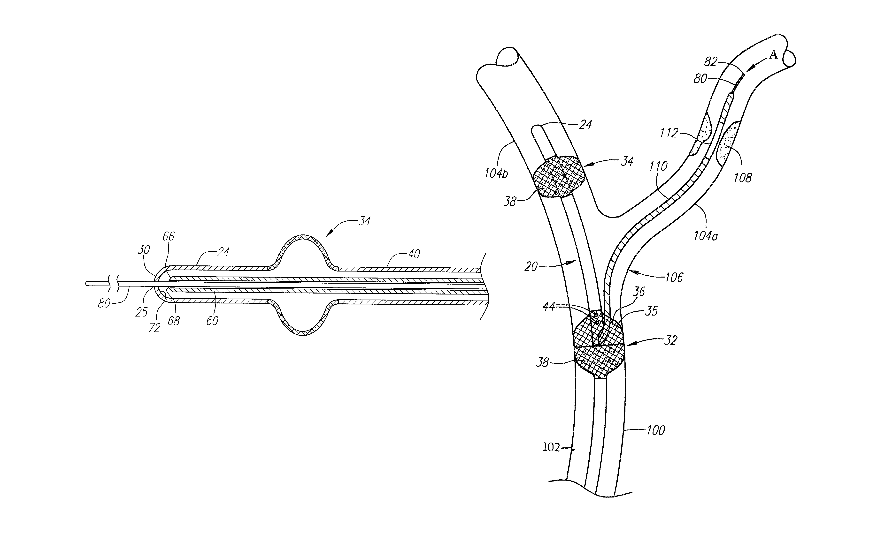
[0067]As used herein, the terms proximal and distal refer to a direction or a position along a longitudinal axis of a catheter or medical instrument. Proximal refers to the end of the catheter or medical instrument closest to the operator, while distal refers to the end of the catheter or medical instrument closest to the patient. For example, a first point is proximal to a second point if it is closer to the operator end of the catheter or medical instrument than the second point.

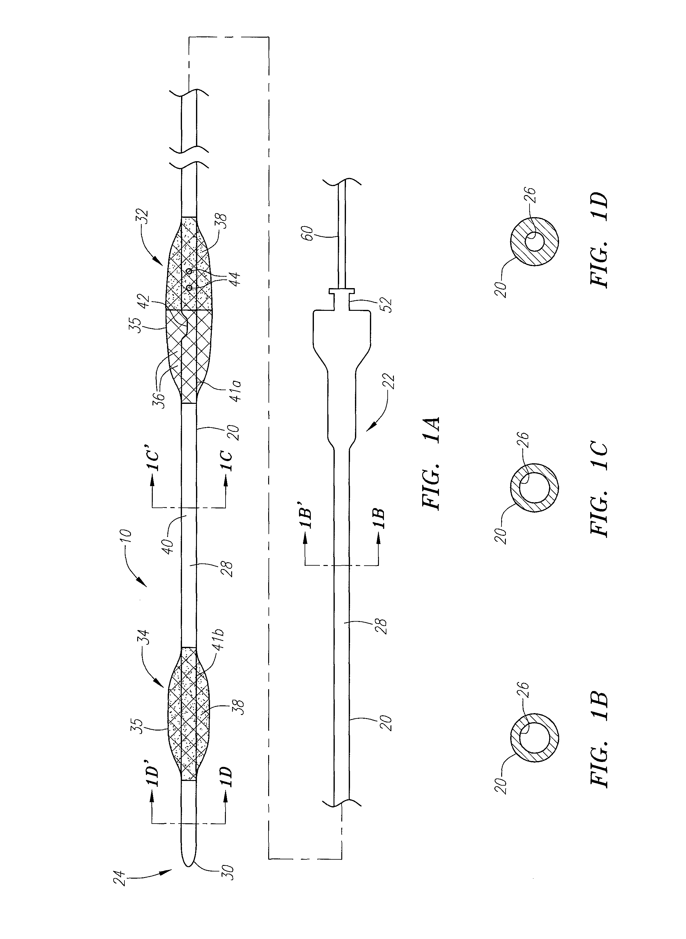
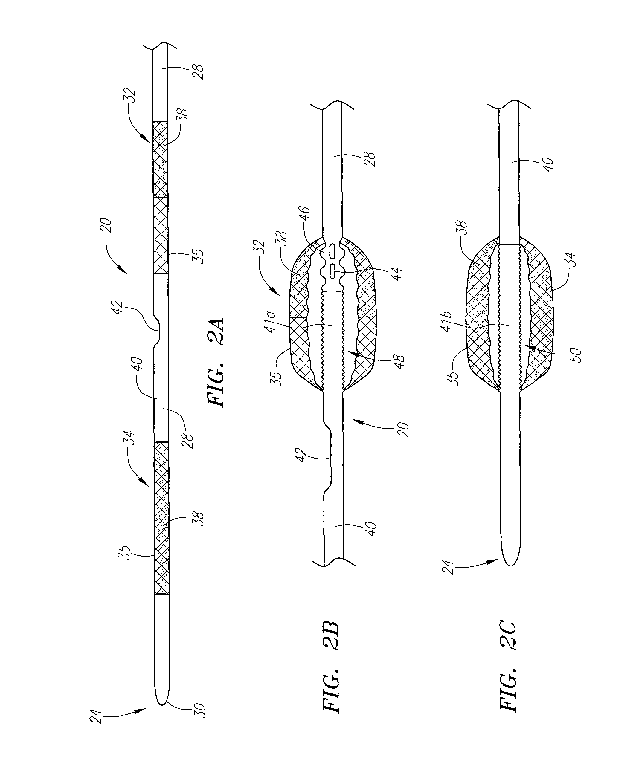
[0068]FIGS. 1A-1D, 2A-2C, 3A, 3B, and 4 illustrate various aspects of a system 10 for the protection of cerebral vessels or brain tissue. The system 10 includes a catheter 20 (illustrated in FIGS. 1A-1D), an elongate stretching member 60 (illustrated in FIGS. 1A, 3A and 3B), and a guidewire 80 (illustrated in FIG. 4). The system 10 can also include one or more additional components used during the interventional procedure. These include, for instance, an introducer or the like (not shown) that is used duri...


PUM


Abstract

A device for protecting cerebral vessels or brain tissue during treatment of a carotid vessel includes a catheter having a distal portion, a proximal portion and a lumen extending therebetween, the catheter including first and second expandable areas for vessel occlusion provided over the length of the catheter. The device further includes an elongate stretching member insertable longitudinally through the lumen of the catheter, the elongate stretching member being configured for stretching at least a portion of the catheter and causing the first and second expandable areas to transition from an expanded state to a collapsed state, and wherein the elongate stretching member is retracted proximally relative to the catheter causes the first and second expandable areas to transition from the collapsed state to a radially, or laterally expanded state.

Description

REFERENCE TO RELATED APPLICATIONS[0001]This Application claims priority to U.S. Provisional Patent Application No. 60 / 890,340 filed on Feb. 16, 2007 pursuant to 35 U.S.C. §119. U.S. Patent Application No. 60 / 890,340 is hereby incorporated by reference as if set forth fully herein.FIELD OF THE INVENTION[0002]The field of the invention generally relates to devices and methods for protecting cerebral vessels and brain tissue during treatment of the carotid vessels. More particularly, the field of the invention pertains to devices and methods for inducing retrograde flow within the carotid vessels so as to eliminate the migration of particulate matter in the direction of normal cerebral blood flow.BACKGROUND OF THE INVENTION[0003]In the case of stenosis in the carotid artery, atherosclerotic plaques are present at the vessel wall of the external carotid artery, the internal carotid artery, or the common carotid artery. These plaques have to be removed as they hinder the blood flow. A nu...

Claims


Application Information

Patent Timeline
Patent Type & Authority Patents(United States)
IPC IPC(8): A61M29/00A61F2/958
CPCA61M25/0054A61M25/007A61M25/01A61M25/0169A61M25/04A61M29/02A61M2025/0183
Inventor BRAUN, MICHAELGEIS, JOHN S.
Owner TYCO HEALTHCARE GRP LP
Why Eureka
Try Eureka