Semiconductor device comprising oxide semiconductor layer

a semiconductor layer and semiconductor technology, applied in the field of semiconductor devices, can solve the problems of high-resistance oxide film formation, affecting transistor characteristics, and carriers left in the oxide semiconductor layer, and achieve the effects of high speed operation, low power consumption, and high reliability of semiconductor devices

Active Publication Date: 2013-01-01
SEMICON ENERGY LAB CO LTD
View PDF152 Cites 66 Cited by
  • Summary
  • Abstract
  • Description
  • Claims
  • Application Information

AI Technical Summary

Benefits of technology

[0019]An object of one embodiment of the present invention is to provide a semiconductor device typified by a display device having higher display quality, in which an adverse effect such as voltage drop, a defect in signal writing to a pixel, a defect in grayscale, and the like due to wiring resistance are prevented.
[0021]Another object of one embodiment of the present invention is to realize reduction in power consumption of a semiconductor device.
[0023]Another object of one embodiment of the present invention is to realize a semiconductor device having excellent yield.
[0036]A semiconductor device capable of high speed operation is provided. In addition, a semiconductor device with low power consumption is provided. Moreover, a highly reliable semiconductor device that operates stably is provided.

Problems solved by technology

A thin film transistor including an oxide semiconductor layer particularly has a problem in that a high-resistance oxide film is formed in a connection interface between the oxide semiconductor and metal.
A thin film transistor including an oxide semiconductor layer particularly has a problem in that carriers which are left in the oxide semiconductor layer affect transistor characteristics.
In addition, there is a problem in that impurities enter the inside of the thin film transistor from the outside after long-term use, resulting in change in transistor characteristics such as a threshold value.
However, since Cu easily diffuses into a semiconductor or silicon oxide, the operation of a semiconductor device might be unstable and yield might be significantly reduced.

Method used


Image

  • Semiconductor device comprising oxide semiconductor layer
  • Semiconductor device comprising oxide semiconductor layer
  • Semiconductor device comprising oxide semiconductor layer

Examples


embodiment 1

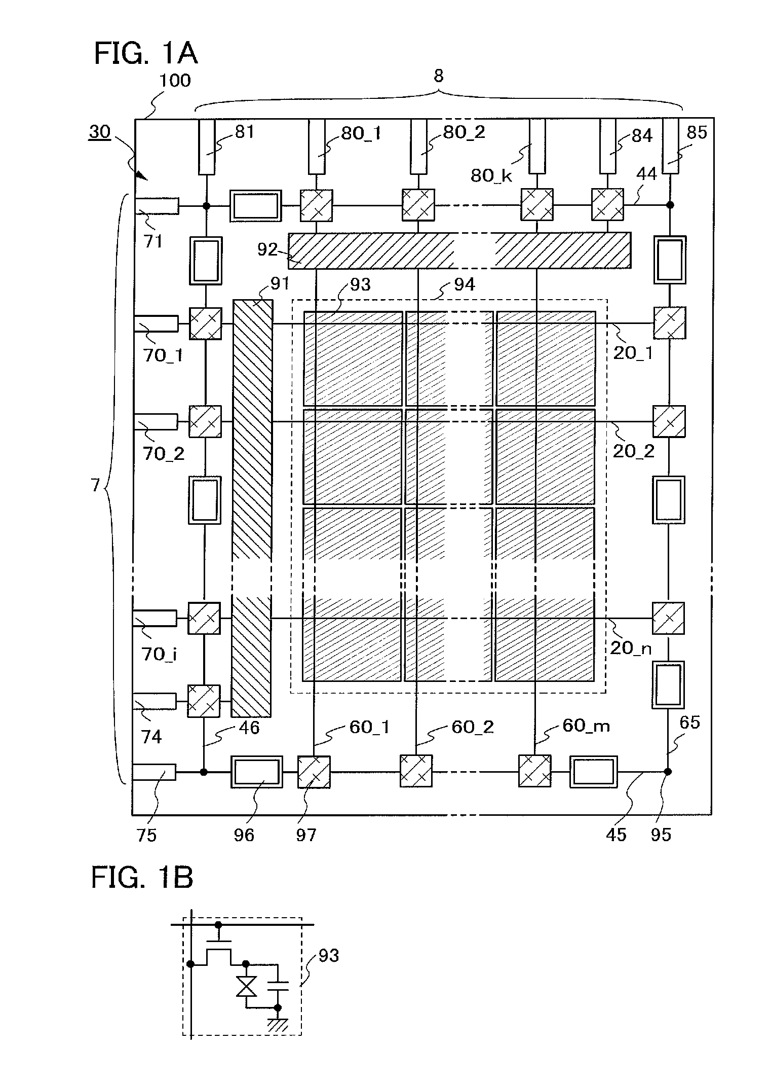
[0088]In this embodiment, one embodiment of a display device in which a pixel portion and a semiconductor element that includes an oxide semiconductor and is provided in the periphery of the pixel portion are formed will be described with reference to FIGS. 1A and 1B.

[0089]FIG. 1A illustrates a structure of a display device 30. The display device 30 includes a gate terminal portion 7 and a source terminal portion 8 over a substrate 100. The display device 30 is provided with gate wirings (20_1 to 20—n (note that n is a natural number)) including the gate wiring 20_1 and the gate wiring 20_2, and source wirings (60_1 to 60—m (note that m is a natural number)) including the source wiring 60_1 and the source wiring 60_2. Further, in a pixel region 94 of the display device 30, pixels 93 are arranged in matrix. Note that each of the pixels 93 is connected to at least one gate wiring and one source wiring.

[0090]Further, the display device 30 includes a common wiring 44, a common wiring 45...

embodiment 2

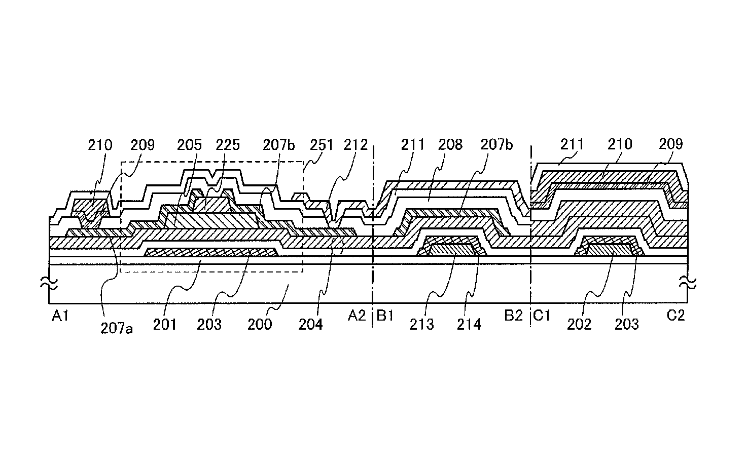
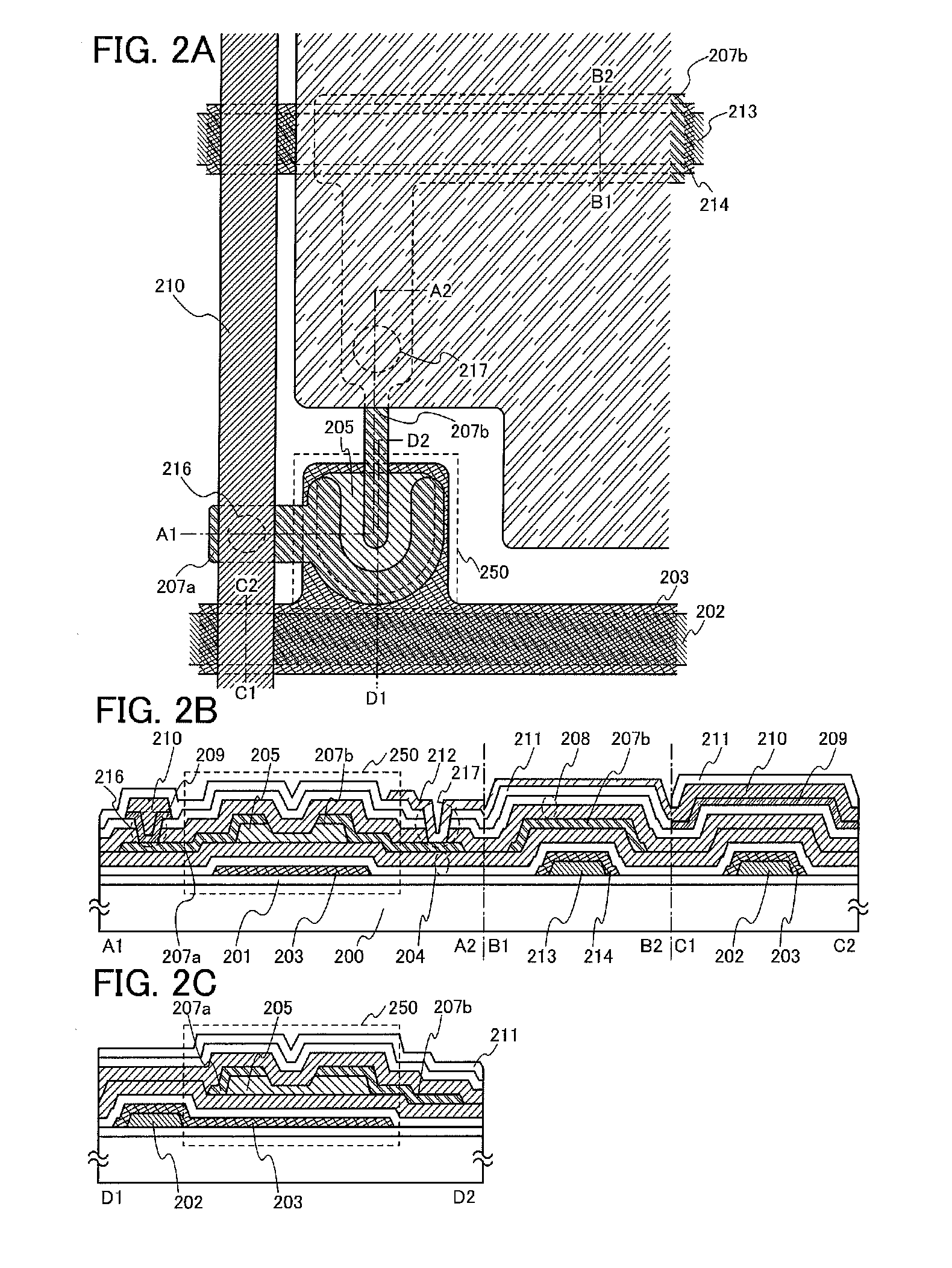
[0111]In this embodiment, a manufacturing process of a pixel portion in the display device described in Embodiment 1 will be described with reference to FIGS. 4A to 4D and FIGS. 5A to 5C. Note that cross section A1-A2, cross section B1-B2, cross section C1-C2, and cross section D1-D2 in FIGS. 4A to 4D and FIGS. 5A to 5C are cross-sectional views taken along chain lines A1-A2, B1-B2, C1-C2, and D1-D2 in FIG. 2A, respectively.

[0112]First, the insulating layer 201 including silicon nitride is formed to a thickness of greater than or equal to 50 nm and less than or equal to 300 nm, preferably greater than or equal to 100 nm and less than or equal to 200 nm over the substrate 200. As the substrate 200, in addition to a glass substrate and a ceramic substrate, a plastic substrate or the like with heat resistance to withstand a process temperature in this manufacturing process can be used. In the case where the substrate does not need a light-transmitting property, a metal substrate, such ...

embodiment 3

[0226]In this embodiment, an example of a structure of a thin film transistor used for the gate driver circuit 91 or the source driver circuit 92 of the display device 30 which is described in Embodiment 1 with reference to FIGS. 1A and 1B will be described.

[0227]A driver circuit for driving a pixel portion is formed using an inverter circuit, a capacitor, a resistor, and the like. In this embodiment, a structure of an inverter circuit which includes two thin film transistors as thin film transistors used in the driver circuit is described. When the inverter circuit is formed using two n-channel TFTs in combination, there are an inverter circuit having two enhancement type TFTs (hereinafter referred to as an EEMOS circuit) and an inverter circuit having a combination of an enhancement type transistor and a depletion type transistor (hereinafter referred to as an EDMOS circuit). Note that an n-channel TFT whose threshold voltage is positive is referred to as an enhancement type trans...


PUM


Abstract

It is an object to provide a semiconductor device typified by a display device having a favorable display quality, in which parasitic resistance generated in a connection portion between a semiconductor layer and an electrode is suppressed and an adverse effect such as voltage drop, a defect in signal wiring to a pixel, a defect in grayscale, and the like due to wiring resistance are prevented. In order to achieve the above object, a semiconductor device according to the present invention may have a structure where a wiring with low resistance is connected to a thin film transistor in which a source electrode and a drain electrode that include metal with high oxygen affinity are connected to an oxide semiconductor layer with a suppressed impurity concentration. In addition, the thin film transistor including the oxide semiconductor may be surrounded by insulating films to be sealed.

Description

TECHNICAL FIELD[0001]The present invention relates to a semiconductor device that includes a thin film transistor (hereinafter also referred to as a TFT).[0002]In this specification, a semiconductor device generally means a device which can function by utilizing semiconductor characteristics, and an electro-optical device, a semiconductor circuit, and an electronic appliance are all semiconductor devices.BACKGROUND ART[0003]In recent years, a technique for forming a thin film transistor (also referred to as a TFT) by using a semiconductor thin film (having a thickness of approximately several nanometers to several hundreds of nanometers) formed over a substrate having an insulating surface has attracted attention. Thin film transistors are applied to a wide range of electronic devices such as ICs or electro-optical devices, and prompt development of thin film transistors that are to be used as switching elements in image display devices, in particular, is being pushed.[0004]A thin f...

Claims


Application Information

Patent Timeline
Patent Type & Authority Patents(United States)
IPC IPC(8): H01L29/10H05B44/00
CPCH01L27/1214H01L27/1225H01L29/45H01L29/78606H01L29/66969H01L27/1288H01L29/78669H01L29/78678H01L29/7869H01L27/124H01L29/4908H01L27/1255H01L29/66742
Inventor YAMAZAKI, SHUNPEIKOYAMA, JUNTAKAHASHI, MASAHIROKISHIDA, HIDEYUKIMIYANAGA, AKIHARUNAKAMURA, YASUOSUGAO, JUNPEIUOCHI, HIDEKI
Owner SEMICON ENERGY LAB CO LTD
Why Eureka
Try Eureka