Synthesis gas method and apparatus

Inactive Publication Date: 2013-01-08
PRAXAIR TECH INC
View PDF13 Cites 84 Cited by
  • Summary
  • Abstract
  • Description
  • Claims
  • Application Information

AI Technical Summary

Benefits of technology

[0021]A heat exchanger can be connected to the oxygen separation device and configured such that the oxygen containing stream is preheated through indirect heat exchange with the heated retentate stream prior to being introduced to the retentate side of the at least one oxygen transport membrane element. The at least one catalytic reactor can have a polishing section situated within a duct that contains a burner fired by a fuel thereby increasing the equilibrium temperature at the outlet of the at least one catalytic reactor and reducing methane slip from such reactor or reactors. The duct burner is positioned between the oxygen separation device and the heat exchanger such that the heated retentate supports combustion of the fuel within the duct burner prior to preheating the oxygen containing stream within the heat exchanger.
[0022]In a specific embodiment of the present invention, the at lea

Problems solved by technology

This is not optimal for the production of synthesis gas for synthetic fuel production such as in Fisher-Tropsch or methanol synthesis where a hydrogen to carbon monoxide ratio of 1.8 to 2.0 within the synthesis gas is more desirable.
As can be appreciated, conventional methods of producing a synthesis gas such as have been discussed above are expensive and complex installations.
Such carbon deposition will degrade reforming catalyst used in connection with the oxygen transport membrane reactor.
The problem with all of these systems is that an oxygen transport membrane will operate at high temperatures of about 900° C. to 1100° C. Where hydrocarbons such as methane and also higher order hydrocarbo

Method used


Image

  • Synthesis gas method and apparatus
  • Synthesis gas method and apparatus
  • Synthesis gas method and apparatus

Examples


Embodiment Construction

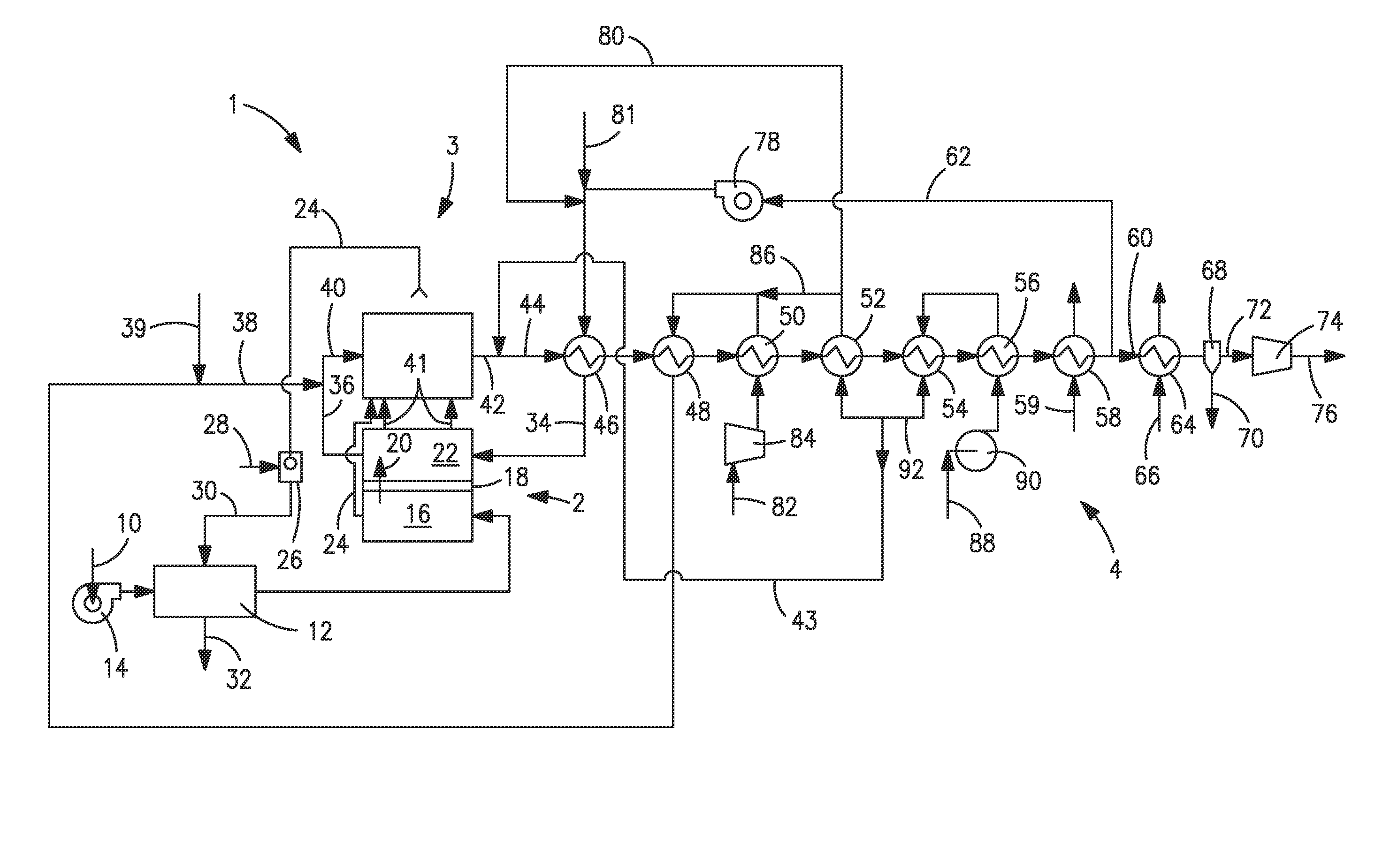
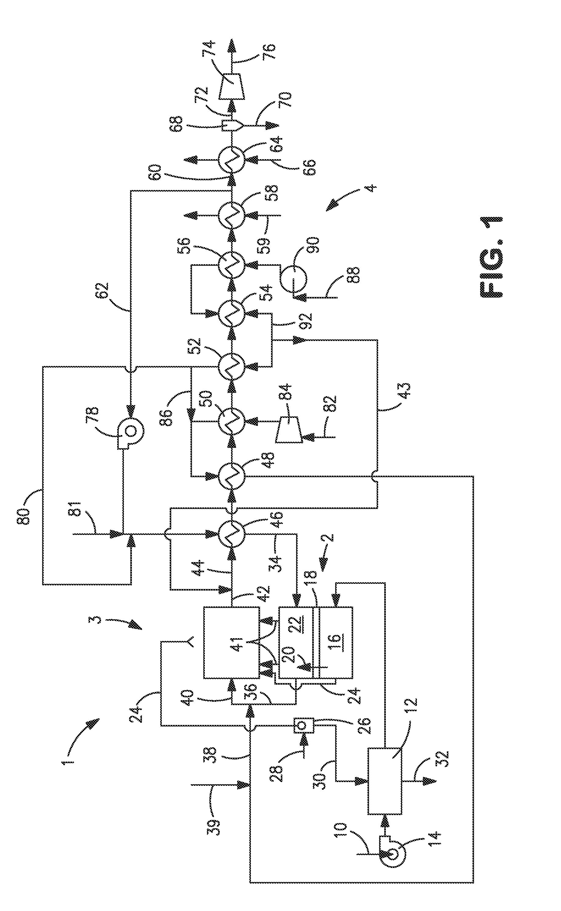
[0041]With reference to FIG. 1, an apparatus 1 is illustrated that is designed to produce a synthesis gas product through the steam methane reforming of hydrocarbons. Apparatus 1 includes one or more oxygen transport membrane elements of which oxygen transport membrane element 2 is illustrated. Oxygen transport membrane element 2 supplies heat by radiation and convective heat transfer to supply the endothermic heating requirements of a catalytic reactor 3 within which the hydrocarbons and steam are reacted to produce a synthesis gas. As well known in the art, at high temperatures, from 700 to 1100° C., steam will react with methane to yield a synthesis gas that contains hydrogen and carbon monoxide. Catalytic reactor 3, as would be known in the art, contains a catalyst, typically nickel, to promote such steam methane reforming reaction. Additionally, water-gas shift reactions occur in which the carbon monoxide will react with the steam to produce carbon dioxide and hydrogen. Althoug...


PUM


Abstract

A method and apparatus for producing a synthesis gas product having one or more oxygen transport membrane elements thermally coupled to one or more catalytic reactors such that heat generated from the oxygen transport membrane element supplies endothermic heating requirements for steam methane reforming reactions occurring within the catalytic reactor through radiation and convention heat transfer. A hydrogen containing stream containing no more than 20 percent methane is combusted within the oxygen transport membrane element to produce the heat and a heated combustion product stream. The heated combustion product stream is combined with a reactant stream to form a combined stream that is subjected to the reforming within the catalytic reactor. The apparatus may include modules in which tubular membrane elements surround a central reactor tube.

Description

[0001]This invention was made with Government support under Cooperative Agreement No. DE-FC26-07NT43088, awarded by the United States Department of Energy. The Government has certain rights in this invention.FIELD OF THE INVENTION[0002]The present invention provides a method and apparatus for producing a synthesis gas product in which a hydrogen containing stream composed of a synthesis gas containing no more than 20 percent by volume methane is reacted with oxygen permeating through an oxygen transport membrane to generate heat to heat the membrane and support endothermic heating requirements of steam methane reforming reactions conducted in a separate catalytic reactor designed to produce the synthesis gas product.BACKGROUND OF THE INVENTION[0003]Synthesis gas containing hydrogen and carbon monoxide is produced for a variety of industrial applications, for example, the production of hydrogen, chemicals and synthetic fuel production. Conventionally, the synthesis gas is produced in...

Claims


Application Information

Patent Timeline
IPC IPC(8): C01B3/38C01B3/26
CPCC01B3/384B01J8/00B01J19/2475B01J19/2485B01J8/0285C01B13/0251C01B2203/0233C01B2203/0238C01B2203/062C01B2203/0822C01B2203/0827C01B2203/0883C01B2203/1058C01B2203/1241B01J2208/00309B01J2208/00504B01J2208/00902B01J2219/00117B01J2219/00157Y02P20/10Y02P20/141
Inventor KELLY, SEAN M.KROMER, BRIAN R.LITWIN, MICHAEL M.ROSEN, LEE J.CHRISTIE, GERVASE MAXWELLWILSON, JAMIE R.KOSOWSKI, LAWRENCE W.ROBINSON, CHARLES
Owner PRAXAIR TECH INC
Why Eureka
Try Eureka