Rapid gas hydrate formation process

a gas hydrate and gas hydrate technology, applied in mechanical equipment, gaseous fuels, fuels, etc., can solve the problems of gas hydrate lattice collapse, gas hydrate nuclei are unstable, and may continue to grow or break in the aqueous solution, so as to reduce the induction time

Inactive Publication Date: 2013-01-15
THE UNITED STATES AS REPRESENTED BY THE DEPARTMENT OF ENERGY
View PDF15 Cites 25 Cited by
  • Summary
  • Abstract
  • Description
  • Claims
  • Application Information

AI Technical Summary

Benefits of technology

[0023]The reaction zone pressure is less than the mixing zone pressure so that the expansion of the hydrate-forming gas which occurs in response to the lower reaction zone pressure provides a degree of cooling by the Joule-Thompson effect. Further, the expansion of the hydrate-forming gas serves to expand water-gas bubbles in the droplets, breaking up the bubbles and producing more intimate mixing between the water and the hydrate-forming gas. The result of the process is the formation of gas hydrates continuously and with a greatly reduced induction time.

Problems solved by technology

The host-lattice is thermodynamically unstable without the presence of a guest molecule in the cavity, and without the support of the trapped molecules, the lattice structure of gas hydrates will collapse into conventional ice crystal structures or liquid water.
If the size of the nuclei is less than the critical size, the nuclei are unstable and may continue to grow or break in the aqueous solution.
Because the water and hydrate forming gas must be maintained at the temperature and pressure condition for hydrate formation during the induction time, this requirement can generate large capital costs and is of paramount importance.
This methodology has been successful in the production of gas hydrates, however the basic approach has disadvantages in both effective cooling and mixing.
The cooling mechanism is mainly based on spray-to-wall heat transfer, and this mechanism may become increasingly ineffective with an increase in the reactor size.
This approach can suffer from formation of a gas hydrate layer on the metal block surface, acting to hindering the heat flow into the block.
However, obstructing the water-circulation loop due to hydrate formation is a significant risk, and the water flow rate through the loop may need to be maintained at an excessively high-level as compared to the rate of water consumption due to the hydrate formation.
This increases the pumping power requirement.
These processes act to decrease bubble size and increase the contact between water in the reactor and the hydrate-forming gas, however the means by which the shear force is generated and applied adds additional mechanical and operational complication to the reactor.
However, many hydrate forming gases such as methane have extremely low solubility in water and the production of a single-phase system consisting of liquid water and a dissolved hydrate-forming gas presents additional difficulties not encountered when hydrate formation can be effectively accomplished using separate phases of liquid water and a gaseous hydrate-former.

Method used


Image

  • Rapid gas hydrate formation process
  • Rapid gas hydrate formation process
  • Rapid gas hydrate formation process

Examples


Embodiment Construction

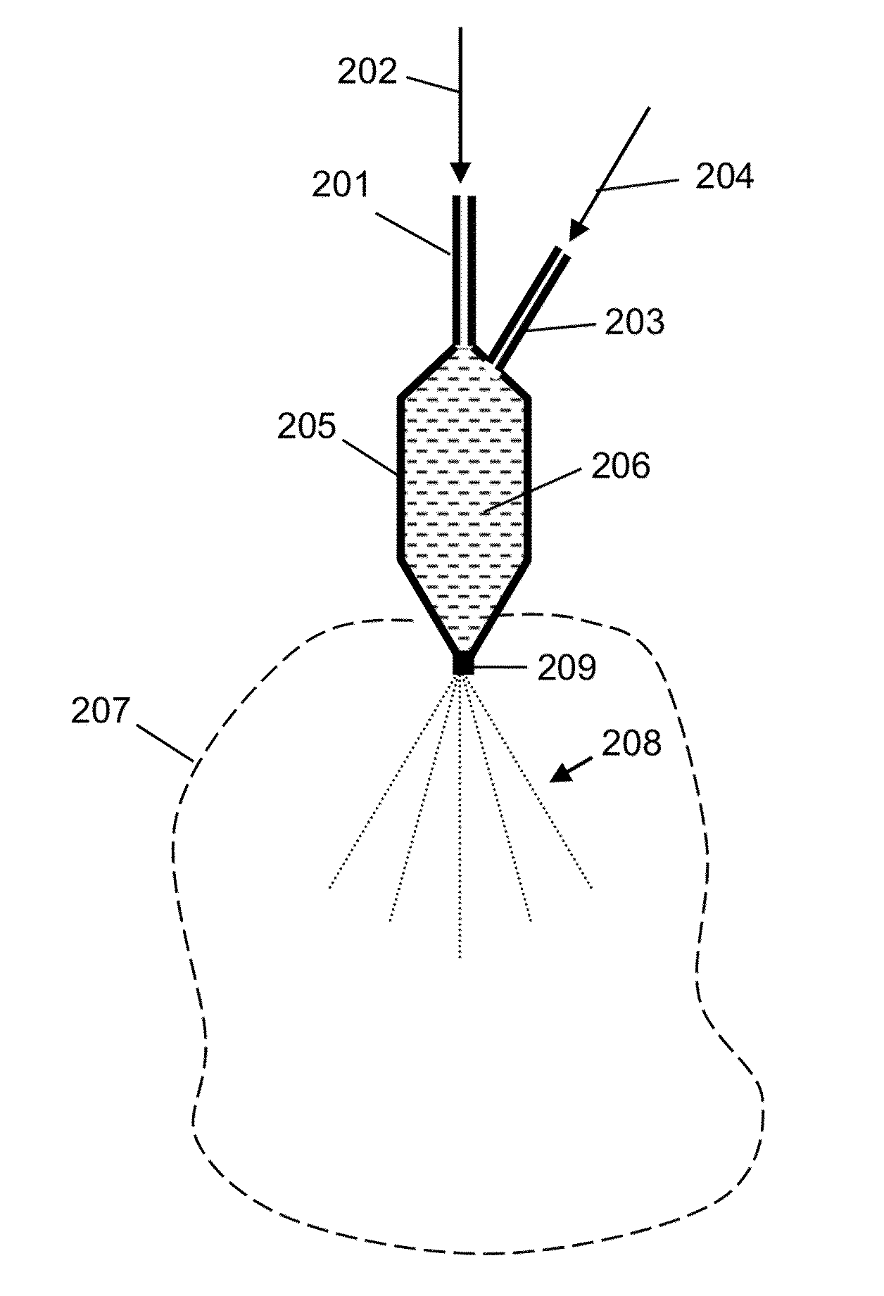
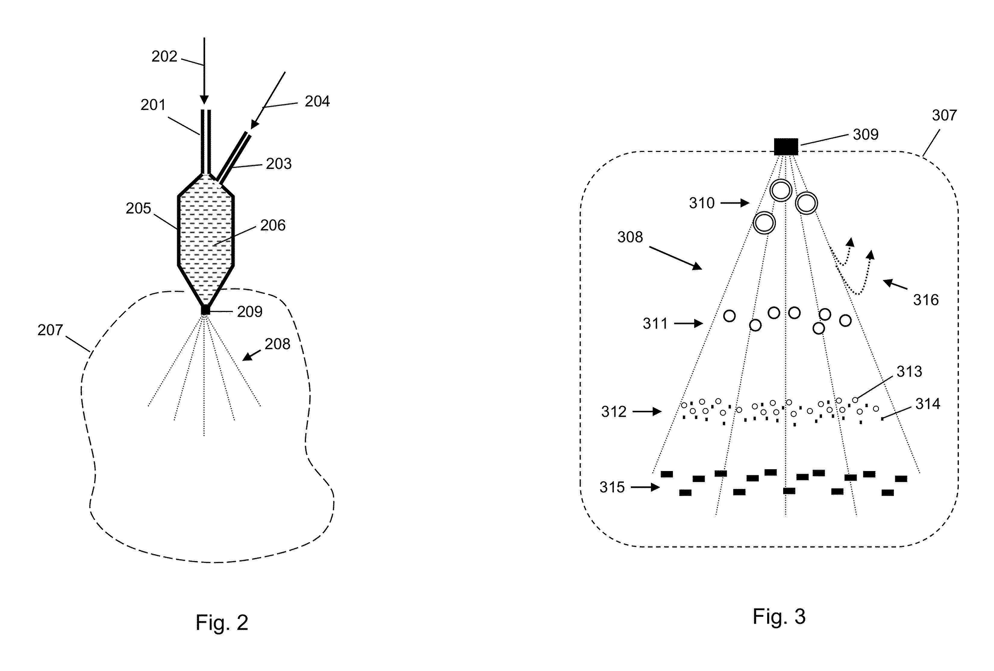
[0035]The following description is provided to enable any person skilled in the art to use the invention and sets forth the best mode contemplated by the inventor for carrying out the invention. Various modifications, however, will remain readily apparent to those skilled in the art, since the principles of the present invention are defined herein specifically to provide a method and apparatus for forming gas hydrates from a two-phase mixture of water and a hydrate forming gas through the introduction of the two-phase mixture into a reaction zone, where the reaction zone is under pressure and temperature conditions suitable for formation of the gas hydrate.

[0036]The method briefly entails:

[0037](a) injecting water into a mixing zone at a water injection rate;

[0038](b) injecting a gaseous stream comprised of a hydrate-forming gas into the mixing zone at a gas injection rate, and forming a water-gas mixture having a water-gas pressure in the mixing zone; and

[0039](c) spraying the wate...


PUM

PropertyMeasurementUnit
diameteraaaaaaaaaa
pressureaaaaaaaaaa
temperatureaaaaaaaaaa

Abstract

The disclosure provides a method and apparatus for forming gas hydrates from a two-phase mixture of water and a hydrate forming gas. The two-phase mixture is created in a mixing zone which may be wholly included within the body of a spray nozzle. The two-phase mixture is subsequently sprayed into a reaction zone, where the reaction zone is under pressure and temperature conditions suitable for formation of the gas hydrate. The reaction zone pressure is less than the mixing zone pressure so that expansion of the hydrate-forming gas in the mixture provides a degree of cooling by the Joule-Thompson effect and provides more intimate mixing between the water and the hydrate-forming gas. The result of the process is the formation of gas hydrates continuously and with a greatly reduced induction time. An apparatus for conduct of the method is further provided.

Description

STATEMENT OF GOVERNMENTAL SUPPORT[0001]The United States Government has rights in this invention pursuant to the employer-employee relationship of the Government to the inventors as U.S. Department of Energy employees and site-support contractors at the National Energy Technology Laboratory.TECHNICAL FIELD[0002]The disclosure provides a method and apparatus for forming gas hydrates from a two-phase mixture of water and a hydrate forming gas. The two-phase mixture is created in a mixing zone which may be wholly included within the body of a spray nozzle. The two-phase mixture is subsequently sprayed into a reaction zone under pressure and temperature conditions suitable for formation of the gas hydrate. The reaction zone pressure is less than the mixing zone pressure so that expansion of the hydrate-forming gas in the mixture provides a degree of cooling by the Joule-Thompson effect and provides more intimate mixing between the water and the hydrate-forming gas. The result of the pro...

Claims


Application Information

Patent Timeline
Patent Type & Authority Patents(United States)
IPC IPC(8): C07C7/20C07C9/00
CPCC07C7/20C10L3/108B01J19/26B01J4/002C07C9/04F17C11/007
Inventor BROWN, THOMAS D.TAYLOR, CHARLES E.UNIONE, ALFRED J.
Owner THE UNITED STATES AS REPRESENTED BY THE DEPARTMENT OF ENERGY
Why Eureka
Try Eureka