
Dielectric ceramic and manufacturing method therefor and laminated ceramic capacitor

a technology of dielectric ceramic and manufacturing method, applied in the field of die, can solve the problems of inability to achieve sufficient reliability and reliability, and achieve the effects of excellent reliability, excellent lifetime characteristic, and grain growth

Active Publication Date: 2013-01-22
MURATA MFG CO LTD
View PDF15 Cites 3 Cited by
  • Summary
  • Abstract
  • Description
  • Claims
  • Application Information

AI Technical Summary

Benefits of technology

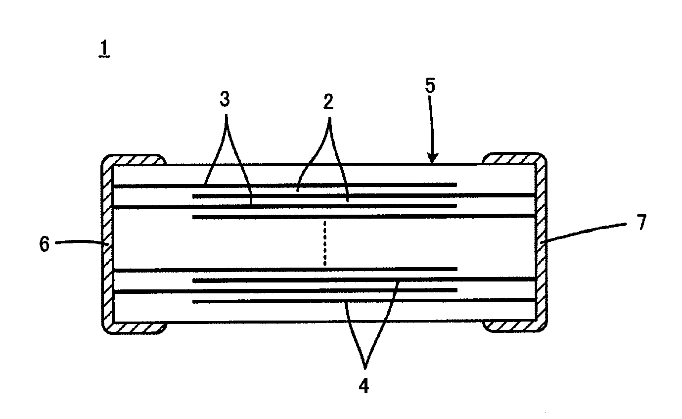
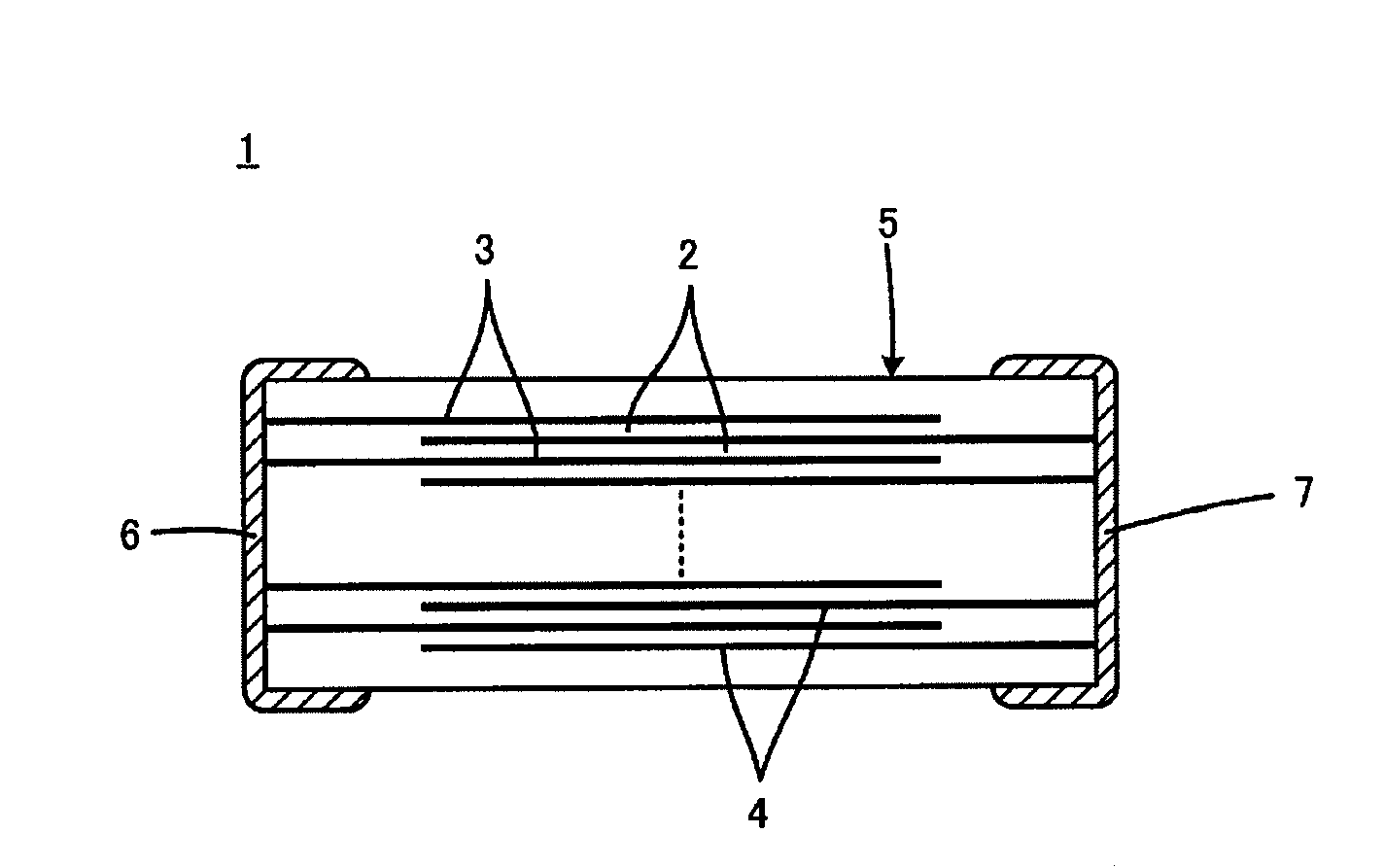
The invention provides a dielectric ceramic with excellent reliability and lifetime characteristic. The ceramic has a small average grain diameter of 0.6 μm or less, which prevents grain growth even when the ceramic layers are thin. The ceramic also contains relatively large amounts of Re and M, which enhance reliability and suppress grain growth. These features make the ceramic suitable for use in laminated ceramic capacitors.

Problems solved by technology

However, there is a problem in that the substitution contents of Gd and Mg are low and both are 3.5 mol % or less, thereby resulting in the inability to achieve sufficient reliability.
Accordingly, as thinning is progressed, the number of crystal grains present in each dielectric ceramic layer will be reduced, easily leading to a problem with reliability.

Method used


Image

  • Dielectric ceramic and manufacturing method therefor and laminated ceramic capacitor
  • Dielectric ceramic and manufacturing method therefor and laminated ceramic capacitor

Examples


experimental example 1

[0048]As staring raw materials for the main component for a dielectric ceramic, respective powders of BaCO3, CaCO3, SrCO3, TiO2, ZrO2, Gd2O3, and MgO were prepared. It is to be noted that a powder with a specific surface area of 11 m2 / g and a powder with a specific surface area of 13 m2 / g were selected respectively as the BaCO3 powder and the TiO2 powder.

[0049]Next, each of the starting raw materials was weighed so as to achieve a composition ratio of (Ba0.89Ca0.01Sr0.01Gd0.10) (Ti0.93Zr0.01Mg0.06) O3.

[0050]Next, for samples 1 to 4 shown in Table 1, 100 g of the weighed raw material powders were each mixed and ground with 130 g of water in a wet manner for 50 hours in a ball mill with PSZ balls of 0.8 mm in diameter, and then dried, calcined in air for 2 hours at each temperature in the range of 950 to 1150° C. shown in the column “Calcination Temperature” of Table 1, to obtain a barium titanate based raw material powder.

[0051]Samples 5 to 8 shown in Table 1 are comparative examples...

experimental example 2

[0073]As staring raw materials supposed to be main components for a dielectric ceramic, respective powders of BaCO3, CaCO3, SrCO3, TiO2 and ZrO2, respective powders of La2O3, CeO2, Pr6O11, Nd2O3, Sm2O3, EU2O3, Gd2O3, Tb4O7, Dy2O3, Ho2O3, Er2O3, Tm2O3, Yb2O3, Lu2O3, and Y2O3 as oxides of Re, and respective powders of MgO, NiO, MnO, Al2O3, Cr2O3, and ZnO as oxides of M were prepared. It is to be noted that the powders with the same specific surface areas as selected in Experimental Example 1 were selected as the BaCO3 powder and the TiO2 powder.

[0074]Next, the starting raw materials were weighed so as to achieve composition ratios shown in Table 2 in terms of (Ba1-h-m-xCahSrmRex)k (Ti1-n-yZrnMy) O3. Next, the weighed raw material powders were mixed and ground in a wet manner in the same way as in Experimental Example 1, and then dried, calcined in air for 2 hours at each temperature in the range of 950 to 1150° C. shown in the column “Calcination Temperature” of Table 2 to obtain a ba...


PUM

PropertyMeasurementUnit
grain diameteraaaaaaaaaa

Abstract

A laminated ceramic capacitor is provided which is excellent in reliability even when its dielectric ceramic layers thinned. For a dielectric ceramic in a laminated ceramic capacitor, a ceramic is used which includes a main component containing a barium titanate based composite oxide represented by the general formula: (Ba1-h-m-xCahSrmRex)k(Ti1-n-yZrnMy)O3, where Re is La or the like, M is Mg or the like, and the respective relationships of 0.05≦x≦0.50, 0.02≦y≦0.3, 0.85≦k≦1.05, 0≦h≦0.25, 0≦m≦0.50, and 0≦n≦0.40 are satisfied; and an accessory component as a sintering aid, wherein the average grain diameter of crystal grains in a sintered body is 0.6 μm or less.

Description

BACKGROUND OF THE INVENTION[0001]1. Field of the Invention[0002]The invention relates to a dielectric ceramic, a method for manufacturing the dielectric ceramic, and a laminated ceramic capacitor composed with use of the dielectric ceramic, and in particular, relates to an improvement for enhancing the reliability of the laminated ceramic capacitor.[0003]2. Description of the Related Art[0004]While a variety of rated voltages are used for laminated ceramic capacitors, high insulation properties (insulation resistance) and reliability (lifetime characteristics in a high temperature load test) are required for the ceramic material constituting dielectric ceramic layers of, in particular, laminated ceramic capacitors to which middle to high voltages (several tens V to several hundreds V) are applied.[0005]In addition, in the past several years, the need for reduction in size of laminated ceramic capacitors has increased. Thus, in order to ensure at least a predetermined capacitance in ...

Claims


Application Information

Patent Timeline
Patent Type & Authority Patents(United States)
IPC IPC(8): H01G4/06C04B35/00
CPCC04B35/462C04B35/47C04B35/49C04B35/6261C04B35/62675C04B35/62685H01G4/1227H01G4/30C01G25/006C04B35/4682Y10T29/435C04B2235/3236C04B2235/442C04B2235/5409C04B2235/6025C04B2235/6584C04B2235/785C01P2004/62
Inventor NISHIMURA, HITOSHIINOUE, NORIYUKIOKAMOTO, TAKAFUMI
Owner MURATA MFG CO LTD
Learn More