CO2 recovery apparatus and CO2 recovery method

a recovery apparatus and co2 technology, applied in the field of co2 recovery apparatus and co2 recovery method, can solve the problem of cosub>2 /sub>recovery extra cost, and achieve the effect of suppressing problems and reducing oxygen concentration

Active Publication Date: 2013-02-19
MITSUBISHI HEAVY IND ENG LTD
View PDF25 Cites 75 Cited by
  • Summary
  • Abstract
  • Description
  • Claims
  • Application Information

AI Technical Summary

Benefits of technology

[0028]According to another aspect of the present invention, a CO2 recovery method includes recovering CO2 using the above described CO2 recovery apparatus, while reducing oxygen concentration in the CO2 gas recovered from the regenerator at a process of compressing the CO2 gas.
[0029]The present invention is made in consideration of the above. An object of the present invention is to provide a CO2 recovery apparatus and a CO2 gas recovery method for reducing concentration of oxygen contained in CO2 that is recovered in a regenerator, and for suppressing problems caused by residual oxygen, such as clogging of equipment or pipes, or coloring of chemical products.

Problems solved by technology

Therefore, extra costs are accrued for CO2 recovery.

Method used


Image

  • CO2 recovery apparatus and CO2 recovery method
  • CO2 recovery apparatus and CO2 recovery method
  • CO2 recovery apparatus and CO2 recovery method

Examples


first embodiment

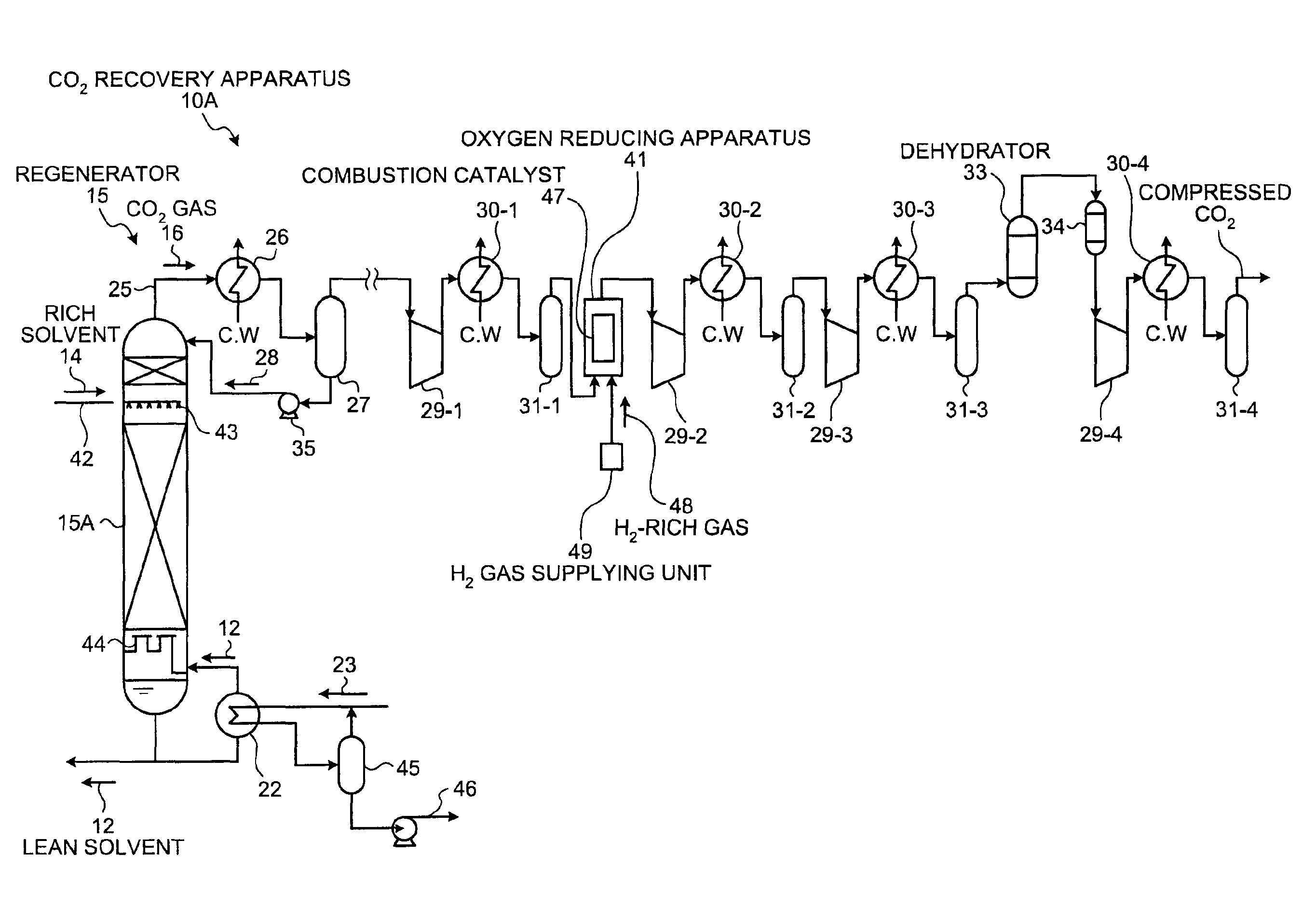
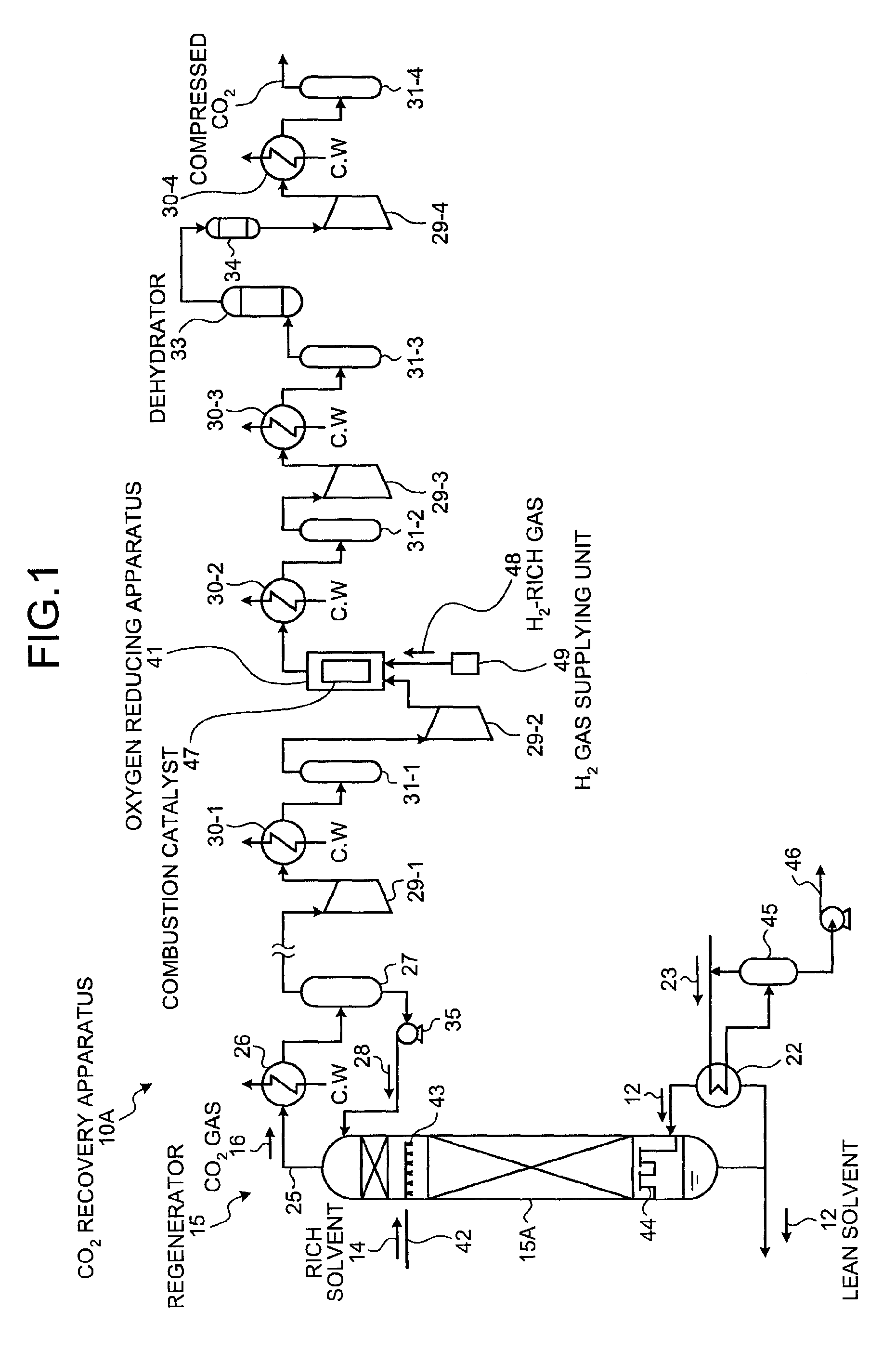
[0038]A CO2 recovery apparatus according to a first embodiment of the present invention will now explained with reference to FIG. 1.

[0039]FIG. 1 is a schematic of the CO2 recovery apparatus according to the first embodiment. In FIG. 1, the same structures as those shown in FIGS. 4 to 7 are assigned with the same reference numerals, and redundant explanations thereof are omitted.

[0040]In the same manner as the CO2 recovery apparatus shown in FIGS. 4 to 7, a CO2 recovery apparatus 10A according to the first embodiment includes a CO2 absorbing system for absorbing CO2 in a CO2 absorber; a CO2 recovery / CO2 absorbing liquid regenerating system for recovering CO2, and regenerating CO2 absorbing liquid in a regenerator; and a CO2 compressing system for compressing the recovered CO2 for injecting the CO2 into underground or an oilfield. The CO2 absorbing system, using CO2 absorber 13 for absorbing CO2, is same as that included in the CO2 recovery apparatus shown in FIGS. 4 and 6; therefore,...

second embodiment

[0064]FIG. 3 is a schematic of a CO2 recovery apparatus according to a second embodiment of the present invention. The CO2 recovery apparatus according to the second embodiment will now be explained with reference to FIG. 3. The same structures as those according to the first embodiment are assigned with the same reference numerals, and redundant explanations thereof are omitted.

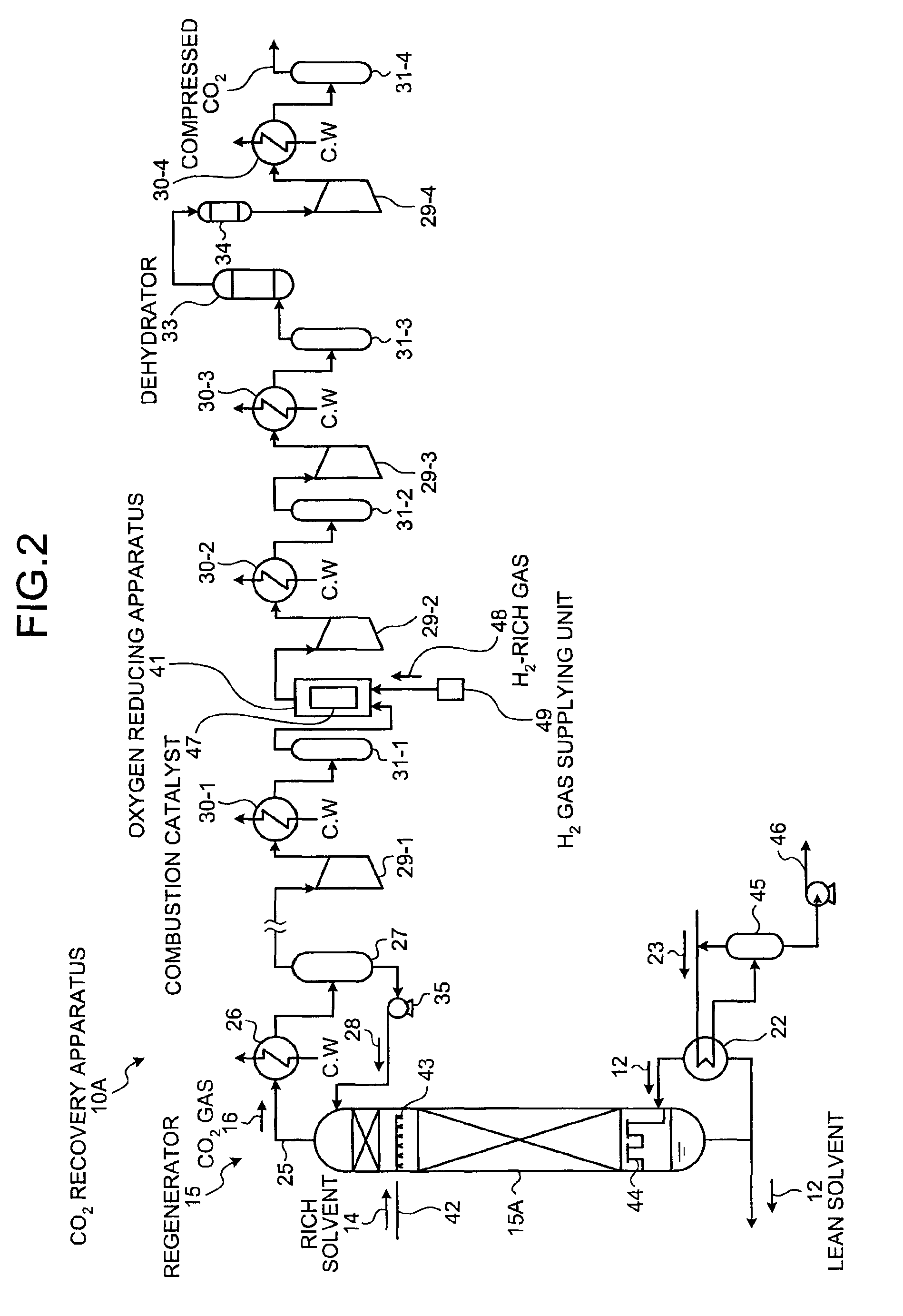
[0065]In a CO2 recovery apparatus 10B according to the second embodiment, the H2 gas supplying unit 49, for supplying the H2-rich gas 48, is arranged between the first separator 31-1 and the second compressor 29-2.

[0066]By introducing the H2-rich gas 48 into the CO2 gas 16 from the H2 gas supplying unit 49 arranged between the first separator 31-1 and the second compressor 29-2, the H2-rich gas 48 can be introduced from the H2 gas supplying unit 49 to the CO2 gas 16 without the pressure thereof being raised any further. In this manner, the CO2 gas 16 can be mixed with the H2-rich gas 48 well, allowing H2 to ...


PUM

PropertyMeasurementUnit
concentrationaaaaaaaaaa
timeaaaaaaaaaa
pressureaaaaaaaaaa

Abstract

A CO2 recovery apparatus according to a first embodiment of the present invention includes: a CO2 absorber that brings flue gas containing CO2 into contact with CO2 absorbing liquid to reduce CO2 in the flue gas; a regenerator that reduces CO2 in CO2 absorbing liquid (rich solvent) that has absorbed the CO2 in the CO2 absorber to regenerate the CO2 absorbing liquid, so that the regenerated absorbing liquid (lean solvent), having CO2 reduced in the regenerator, is reused in the CO2 absorber; a first compressor to a fourth compressor that compress the CO2 gas released from the regenerator; and an O2 reducing apparatus arranged between the second compressor and a second cooler to reduce O2 in the CO2 gas.

Description

BACKGROUND OF THE INVENTION[0001]1. Field of the Invention[0002]The present invention relates to a CO2 recovery apparatus and a CO2 recovery method for reducing CO2 in flue gas by allowing CO2 absorbing liquid to absorb CO2 contained in the flue gas, and for regenerating and reusing the CO2 absorbing liquid.[0003]2. Description of the Related Art[0004]It has come to be pointed out that one of the causes of the global warming is a greenhouse effect of CO2, and it has become an urgent task, also internationally, to provide a countermeasure for CO2 to protect the global environment against the warming. CO2 is generated by any human activities combusting fossil fuels, and there are increasing demands for suppressing CO2 emissions. Along with such an increasing demand, researchers are energetically investigating for a method for reducing and recovery CO2 included in flue gas to apply in a power plant that consumes a large amount of fossil fuels, such as a thermal plant. In such a method,...

Claims


Application Information

Patent Timeline
Patent Type & Authority Patents(United States)
IPC IPC(8): B01D53/14C01B32/50
CPCB01D53/1425B01D53/1475Y02C10/06Y02C10/04Y02C20/40
Inventor FUJIKAWA, KEIJIHIRATA, TAKUYATSUJIUCHI, TATSUYAOISHI, TSUYOSHI
Owner MITSUBISHI HEAVY IND ENG LTD
Why Eureka
Try Eureka