
Radio transmitting apparatus and radio transmitting method

a technology of radio transmission and apparatus, applied in the field of radio transmission apparatus and radio transmission method, can solve the problems of increasing processing delay of association request processing to bs, processing delay by acquiring uplink transmission timing synchronization including ra burst, etc., and achieve the effect of improving throughput and speeding up initial access processing

Inactive Publication Date: 2013-02-19
SOVEREIGN PEAK VENTURES LLC
View PDF19 Cites 11 Cited by
  • Summary
  • Abstract
  • Description
  • Claims
  • Application Information

AI Technical Summary

Benefits of technology

The present invention aims to enhance the speed and efficiency of processing, particularly in relation to RA burst transmission. It is designed to facilitate faster and more scalable data processing.

Problems solved by technology

When RA burst collision and reception error occur, the processing delay by acquiring uplink transmission timing synchronization including RA bursts and processing delay for association request processing to BS, increase.

Method used


Image

  • Radio transmitting apparatus and radio transmitting method
  • Radio transmitting apparatus and radio transmitting method
  • Radio transmitting apparatus and radio transmitting method

Examples


embodiment 1

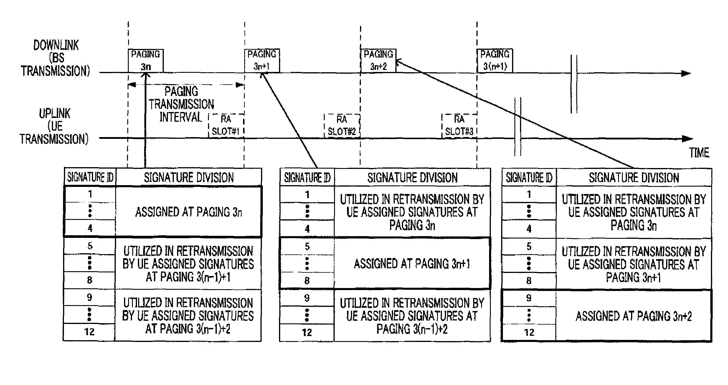
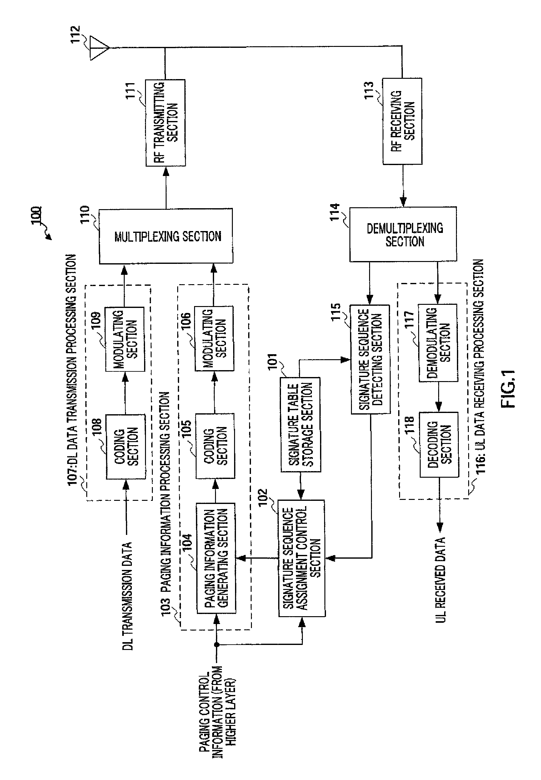
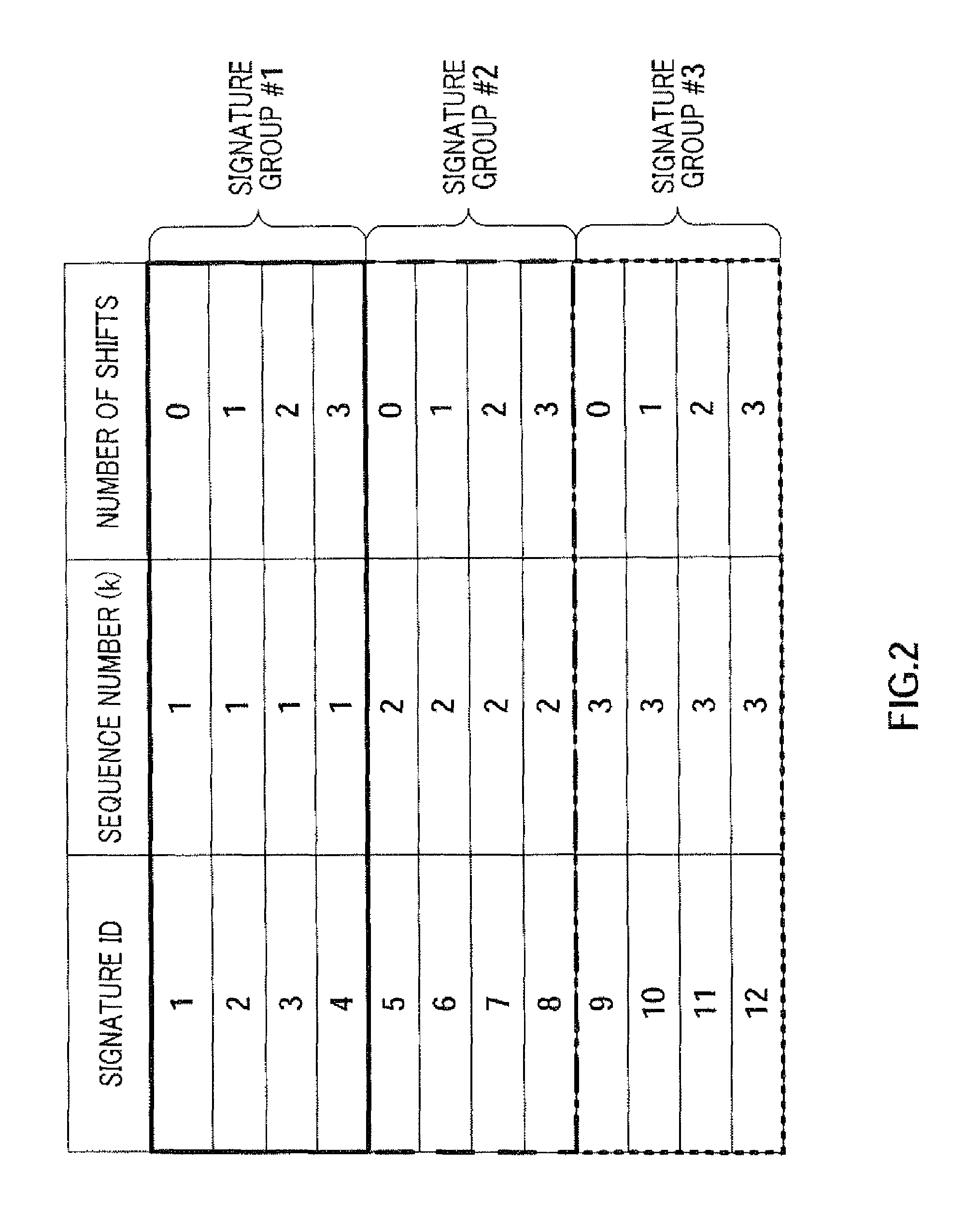
[0030]FIG. 1 is a block diagram showing the configuration of base station apparatus 100 according to Embodiment 1 of the present invention. In this figure, a plurality of signatures generated from a single Zadoff-Chu sequence form a single group (hereinafter “signature group”), and signature table storage section 101 stores a plurality of signature groups generated from a plurality of different Zadoff-Chu sequences. Further, the signature table will be described later in detail.

[0031]Signature sequence assignment control section 102 acquires the identity of the UE targeted for paging from the higher layer (not shown), while reading out a signature sequence from signature table storage section 101 and assigning the read signature sequence to the UE of the paging target. Further, according to a detection result outputted from signature sequence detecting section 115, which will be described later, signature sequence assignment control section 102 decides whether or not to retransmit R...

embodiment 2

[0089]The configurations of the BS and UE according to Embodiment 2 of the present invention are the same as the configurations shown in FIG. 1 and FIG. 3 of Embodiment 1, and will be explained using FIG. 1 and FIG. 3.

[0090]First, in the Zadoff-Chu sequences shown in Embodiment 1, the cross-correlation characteristics between two different sequence numbers k=k1 and k=k2 will be explained. The cross-correlation characteristics have the following relationships. When the greatest common divisor between |k1−k2| and N is one, the peak value of cross-correlation is √N. Further, when the greatest common divisor between |k1−k2| and N is not one, the peak value of the cross-correlation is greater than √N. Further, the peak value of cross-correlation increases in proportion to the scale of the greatest common divisor.

[0091]Although the greatest common divisor between |k1−k2| and N is one with respect to all k's when the sequence length N is a prime number, the sequence length N needs to hold ...


PUM


Abstract

A radio transmitting apparatus and a radio transmitting method wherein the throughput is improved and a fast initial access processing including an RA burst is accomplished. According to these apparatus and method, a signature table storing part (101) has a plurality of signature groups generated from a plurality of different Zadoff-Chu sequences with a set of signatures generated from one Zadoff-Chu sequence being one signature group. A signature sequence assignment control part (102) switches signature groups to be assigned to a UE for each of paging transmissions, thereby assigning a signature sequence, which is to be used for an initial RA, from the same signature group. A paging information generating part (104) causes the ID of the assigned signature sequence to be included into paging information, which is then transmitted to the UE.

Description

TECHNICAL FIELD[0001]The present invention relates to a radio transmitting apparatus and radio transmitting method.BACKGROUND ART[0002]In mobile communication systems represented by a cellular communication system or radio LAN (Local Area Network) system, random access areas are provided in the transmission domain. When a terminal station (hereinafter “UE”) implements an association request to a base station (hereinafter “BS”) at first, or when a UE implements a new band assignment request in a centralized control system where, for example, the BS assigns transmission time and transmission frequency band to the UE, random access areas are provided in the uplink. Here, a base station is also referred to as an “access point” or “Node B.”[0003]Further, in systems adopting TDMA (Time Division Multiple Access), which is currently standardized in 3GPP RAN LTE, when the initial association request is implemented (i.e., when the power supply of a UE is activated, and further when handover i...

Claims


Application Information

Patent Timeline
Patent Type & Authority Patents(United States)
IPC IPC(8): H04L12/413H04J13/00H04J13/18H04J13/22
CPCH04J13/0062H04J13/0074H04J13/22H04W8/26H04W48/08H04W68/00H04W72/04H04W74/08H04W72/20H04W74/0833
Inventor IMAMURA, DAICHIFUTAGI, SADAKIMATSUMOTO, ATSUSHIIWAI, TAKASHIOGAWA, YOSHIHIKO
Owner SOVEREIGN PEAK VENTURES LLC
Learn More