System metrology core

a metrology core and photolithography technology, applied in the field of photolithography systems, can solve the problems of slow thermal compensation, adversely affecting image quality, and large error source of heating and cooling of the lens by the illumination source, so as to facilitate the expansion/contraction of components, facilitate the coordination of multiple images, and reduce the effect of thermal compensation

Active Publication Date: 2013-03-12
ONTO INNOVATION INC
View PDF19 Cites 10 Cited by
  • Summary
  • Abstract
  • Description
  • Claims
  • Application Information

AI Technical Summary

Benefits of technology

[0011]Mechanically decoupling the metrology plate (system metrology core) from the projection optics allows simultaneous formation and accurate coordination of multiple images on a single substrate. For example, decoupled metrology plates can be used to estimate the positions of images associated with two or more projection optics relative to the surface of a single substrate. In addition, mechanically decoupling the metrology plate from the projection optics provides added design flexibility, including space for additional sensors, and relaxes constraints on expansion / contraction of components due to heating, etc.
[0012]Fundamentally, a decoupled metrology plate (system metrology core) allows greater design flexibility to make a super-stable, robust reference base for all the important coordinate systems in the system. It eases stability tolerances on other subsystems and structures, such as the camera / lens. Also, the mass and weight distribution needed to create a suitably stable metrology plate could have a detrimental effect if mounted to the camera or objective; the decoupled metrology plate according to this embodiment of the invention enables stability without negatively impacting other system components.

Problems solved by technology

Even minute changes in the relative positions and attitudes of the reticle, lens, and substrate can adversely affect the image quality.
In mechanically stable systems, heating and cooling of the lens by the illumination source may be the largest source of error.
Unfortunately, thermal compensation is slow, and interferometric measurement requires bulky equipment and optical access to the substrate or the substrate stage.
Although this is a simple way of measuring defocus in real time, monitoring focus change in this way at only one radius in the field does not ensure determination of higher-order aberrations, such as astigmatism and field curvature.
This complicates the design because either or both the production pattern to be printed and the substrate interfere with the optical and mechanical design.
In addition, fixing the camera (and the metrology plate) to the lens limits the flexibility of the system by increasing the bulk and mass of the lens assembly.

Method used


Image

  • System metrology core
  • System metrology core
  • System metrology core

Examples


Embodiment Construction

[0026]A description of example embodiments of the invention follows.

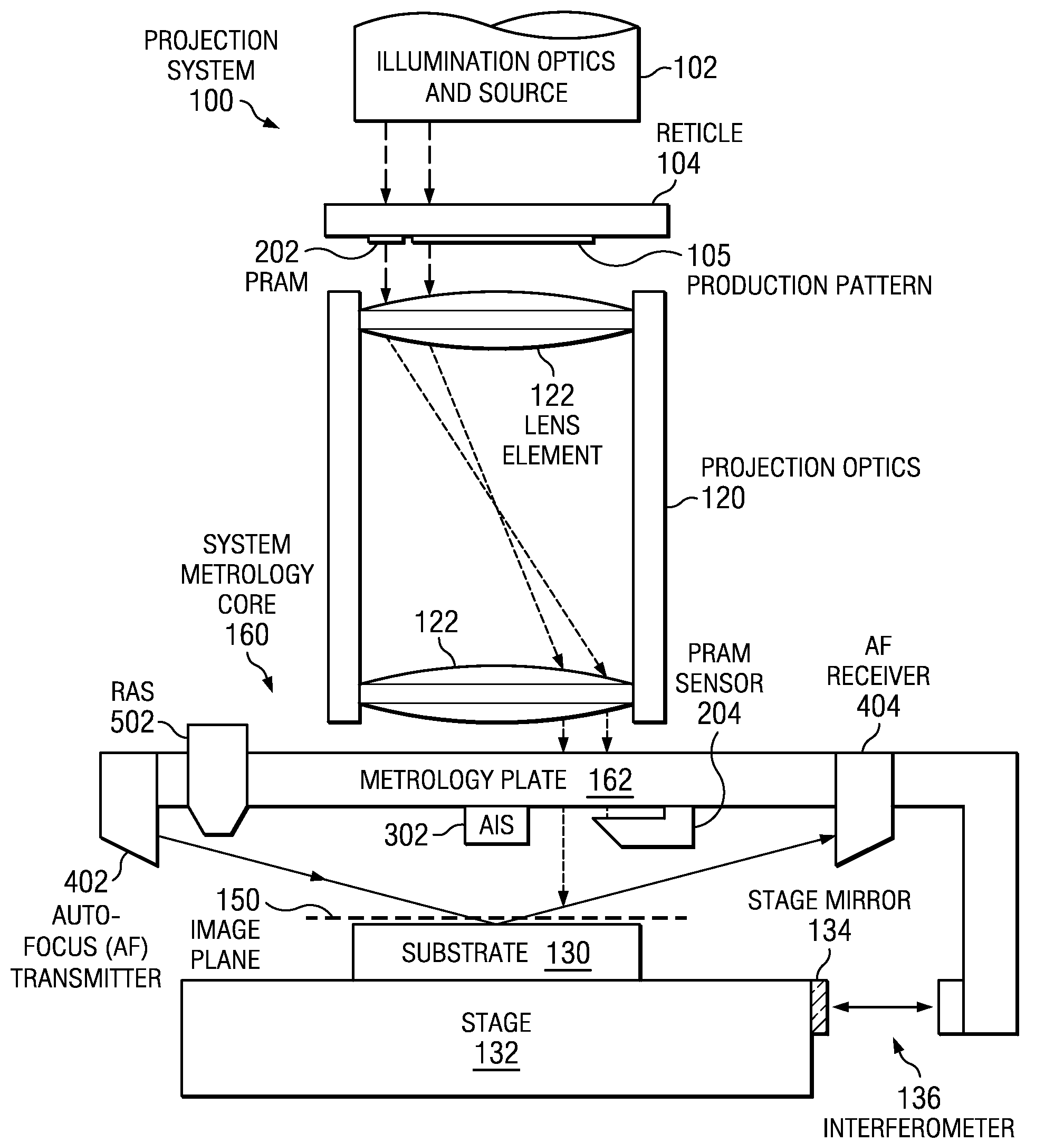
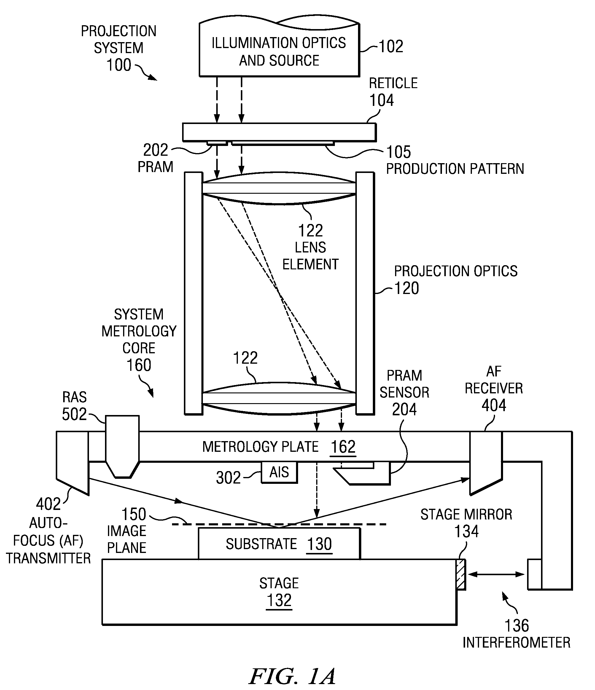
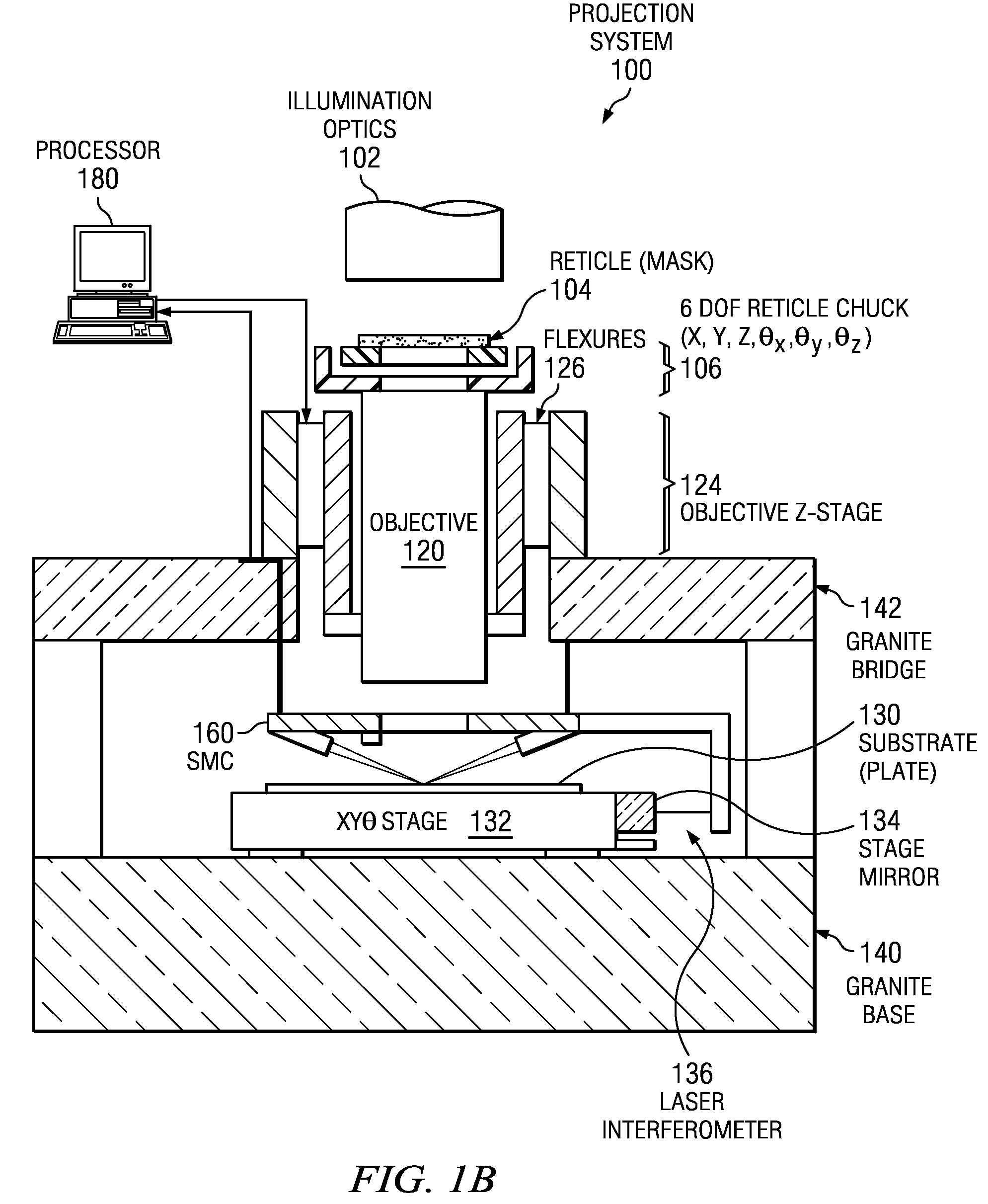
[0027]FIGS. 1A and 1B show a projection system 100 that can be used to pattern a substrate 130, such as a wafer of semiconductor or a piece of glass, with a production pattern 105 on a reticle 104. Projection optics 120 image the production pattern 105 from the reticle 104, which is illuminated by an illumination source 102, to an image 150. Turning on the illumination source 102 exposes photoresist (not shown) on the substrate 130 to a dose of illumination in the image of the production pattern 104. After exposure, the production pattern 105 may be exchanged for a different pattern by switching the reticle 104 and / or the substrate 130 may be replaced or moved to a new location with a stage 132.

[0028]Ideally, the image 150 is coincident with one of the surfaces of the substrate 130. If the substrate 130 is a piece of glass coated with indium tin oxide (ITO) and photoresist, for example, the image may be coincident w...


PUM


Abstract

Projection systems and methods with mechanically decoupled metrology plates according to embodiments of the present invention can be used to characterize and compensate for misalignment and aberration in production images due to thermal and mechanical effects. Sensors on the metrology plate measure the position of the metrology plate relative to the image and to the substrate during exposure of the substrate to the production image. Data from the sensors are used to adjust the projection optics and / or substrate dynamically to correct or compensate for alignment errors and aberration-induced errors. Compared to prior art systems and methods, the projection systems and methods described herein offer greater design flexibility and relaxed constraints on mechanical stability and thermally induced expansion. In addition, decoupled metrology plates can be used to align two or more objectives simultaneously and independently.

Description

BACKGROUND OF THE INVENTION[0001]In photolithography systems, projection optics form an image of an illuminated object, such as a reticle, on a substrate, such as a semiconductor wafer or flat panel display substrate, that is coated with a photoresist. Illuminating the photoresist to expose the substrate, then etching the exposed substrate causes a pattern to form on the substrate that mimics the image with a resolution determined by the optical system and the size of the features on the reticle. At present, the desired feature size for applications in the semiconductor and flat panel display industries is under three microns and continues to shrink.[0002]Even minute changes in the relative positions and attitudes of the reticle, lens, and substrate can adversely affect the image quality. In mechanically stable systems, heating and cooling of the lens by the illumination source may be the largest source of error. During exposure, the lens absorbs some of the light from the illuminat...

Claims


Application Information

Patent Timeline
Patent Type & Authority Patents(United States)
IPC IPC(8): G01B11/14
CPCG03F7/706G03F7/70833G03F7/7085G03F7/70891
Inventor DONAHER, J. CASEYSIMPSON, CRAIG R.MCCLEARY, ROGER
Owner ONTO INNOVATION INC
Why Eureka
Try Eureka