Cargo restraint system with enhanced reinforcement filament break strength content

a technology of reinforced filament and cargo, which is applied in the direction of load securing, transportation and packaging, transportation of items, etc., can solve the problems of large transport load, large momentum force, and potential to impart substantial damage to contents within intermodal containers, and cargo tends to build up considerable momentum

Active Publication Date: 2013-03-26
MBULL HLDG LLC
View PDF59 Cites 17 Cited by
  • Summary
  • Abstract
  • Description
  • Claims
  • Application Information

AI Technical Summary

Benefits of technology

[0016]It is a general object that the subject invention provide a novel system and method to secure a load within an intermodal container, or the like, which will obviate or minimize problems and concomitantly achieve at least some of the desired aspects of efficient lading securement within a container.
[0017]It is another general object of the invention to judiciously protect cargo from damage during transport and to provide enhanced efficiency securement of a load within a container while minimizing shifting of a container load.
[0018]It is a further object of the invention to provide a securement system for an intermodal container, and the like, with enhanced cost efficiency with respect to securing lading to the sidewalls of an intermodal container, air container, rail car, trailer and the like during transport.
[0019]It is a specific object of the subject invention to optimize the use of lashing filament strand break strength with reduced costs while maintaining operational characteristics necessary to secure lading within an intermodal container, and the like.BRIEF SUMMARY OF THE INVENTION
[0024]Finally, a layer of release material extends coextensively with and is releasably adhered to the second side surface of the second layer of adhesive applied to the second side of the layer of reinforcement. The layer of release material may be removed from the second layer of adhesive on site of use and the load restraining strip is operable to be releasably affixed to a side wall surface of a cargo transport container such that the load restraining strip may be used as a flexible securement element to secure cargo within a transport container with enhanced filament break strength efficiency characteristics.

Problems solved by technology

Although each containment enclosure may be quite heavy and stationary at rest, the mass of a transport load can produce considerable momentum force as a result of ship, aircraft, railcar, or truck changes in motion such as for example by acceleration, deceleration or a change in direction.
Each of these forces has the potential to impart substantial damage to contents within the intermodal container.
Without some type of restraint and / or cushioning system, cargo tends to build up considerable momentum, independent of the container.
In the case of large cargo loads, even a small change in velocity or direction can generate substantial motion forces.
For air travel, although commercial passenger flights avoid air turbulence, in some instances clear air turbulence or even rough weather is not avoidable.
When a railroad car is rolled into a stationary string of cars, the impact causes the car couplings to lock together with a jolt.
Moreover, during transport, railway cars are subject to braking forces, run-in and run-out, coupler impact over grades, rail vibration, dips in the track, and swaying.
In a similar manner trucks are subject to stopping and starting forces, emergency braking, bumps and swaying from uneven road beds, centrifugal forces on curves, vibration, etc. all of which tend to shift gravity secured loads within a container.
Such forces can result in damage to cargo, damage to interior walls or doors of the container, damage to cargo packing, and moreover may create dangerous leaks if the cargo is a hazardous material.
Accordingly, it is undesirable to permit cargo to gain any momentum independent of a container during transport.
All of these previously known systems for securement have limitations associated with construction cost, lack of strength sufficient to secure dense loads, etc.
Moreover, although rear doors of a truck trailer may be relied on to at least partially secure non-hazardous materials such as food-stuffs, tissue or soft paper products, furniture, appliances, etc., for hazardous materials, and many other types of loads, the rear doors of a container may not be used to even partially secure a load.
This, however, can be a costly, time consuming, and generally inefficient means of securing a load.
A lumber based bracing and blocking process requires skilled carpenters and is often outsourced to contractors.
Moreover, wooden barriers can be time consuming to install.
Wood bracing can be somewhat brittle and subject to failure as a result of an abrupt impact.
Further conventional methods of load-blocking with lumber bracing simply can not perform some tasks.
However, if eighty barrels are loaded there are only approximately four inches between the load face and rear doors of a conventional intermodal container.
Four inches is not enough space to put sufficient lumber to brace a load of eighty drums adequately.
Consequently, when wood bracing is utilized as a system of restraint, shippers are forced to ship containers that are not filled to capacity.
This reduces transport efficiency and increases transportation costs.
Moreover, some types of wood, such as conifer woods, are not acceptable to cross international boundaries without certification of special fumigation or heat treatment processing.
In certain instances, conventional load-locking and lumber bracing has not been structurally rugged enough to receive approval to ship hazardous cargo.
Other known means of restraint such as ropes, metal or plastic straps or stands and the like appearing in the past have tended to be expensive, exhibit impaired performance and are often not functionally suitable to restrain desired loads.
In this instance it may be impractical to construct wooden front and rear dunnage sufficient to secure a load where the front of the trailer is not utilized.
Additionally some partial loads are not symmetrically positioned on a pallet and securement must therefore accommodate an asymmetric load situation.
The limitations suggested in the preceding and / or desirable characteristics for advantageous load restraint systems are not intended to be exhaustive but rather are among many which may tend to reduce the effectiveness or desirability of cargo restraining systems known in the past.

Method used


Image

  • Cargo restraint system with enhanced reinforcement filament break strength content
  • Cargo restraint system with enhanced reinforcement filament break strength content
  • Cargo restraint system with enhanced reinforcement filament break strength content

Examples


Embodiment Construction

Context of the Invention

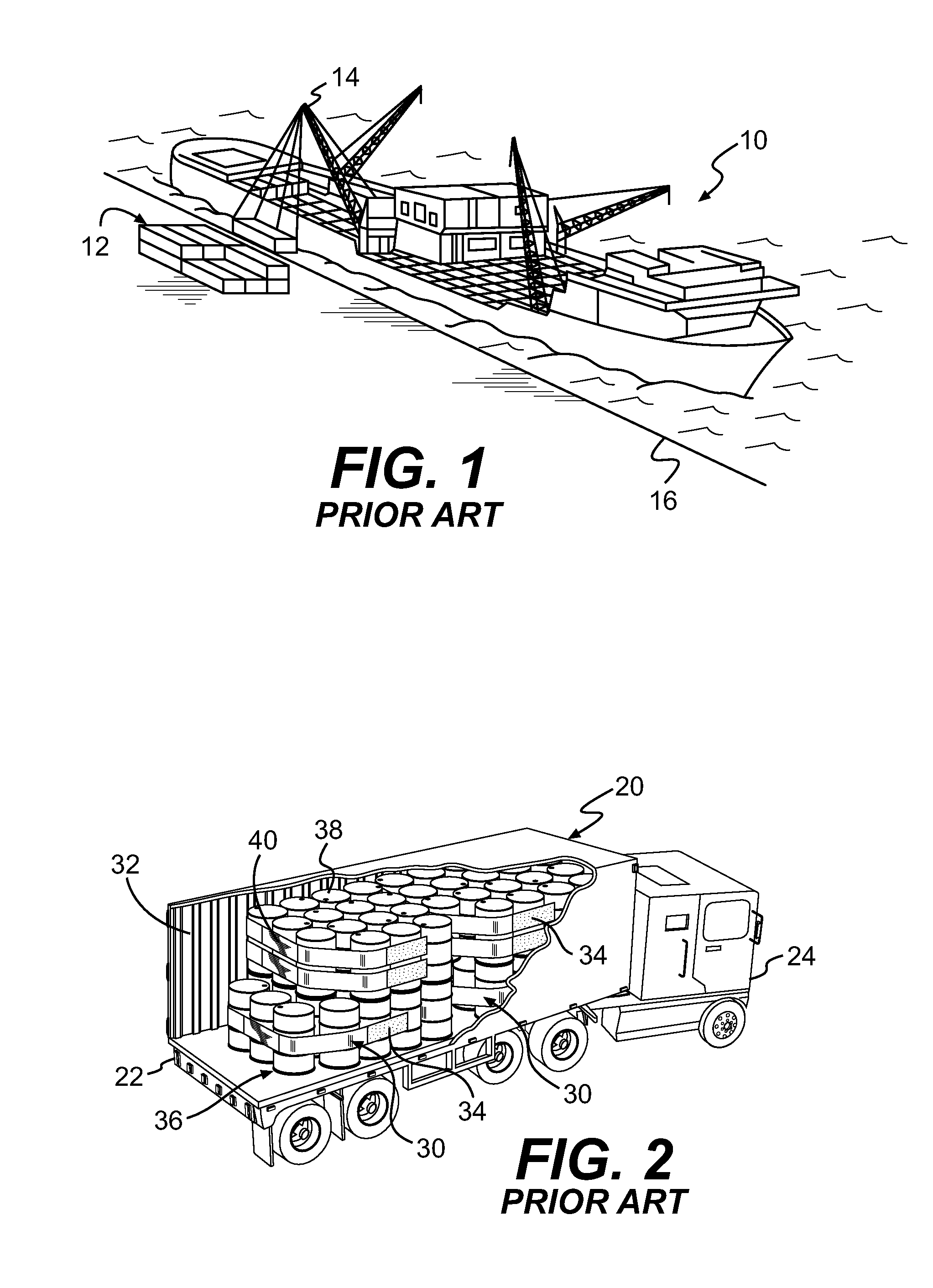
[0036]Referring now particularly to FIG. 1, a schematic illustration depicts an ocean going vessel 10 docked at a port and intermodal containers 12 are being loaded onto the ship. Cranes 14 mounted on board the ship or on the dock 16 are shown stacking intermodal containers on top of each other and the containers are ruggedly secured on the deck of the ocean going vessel 10. The subject invention may be advantageously used to secure cargo within the intermodal containers 12 or air transport containers, rail cars, truck trailers and the like.

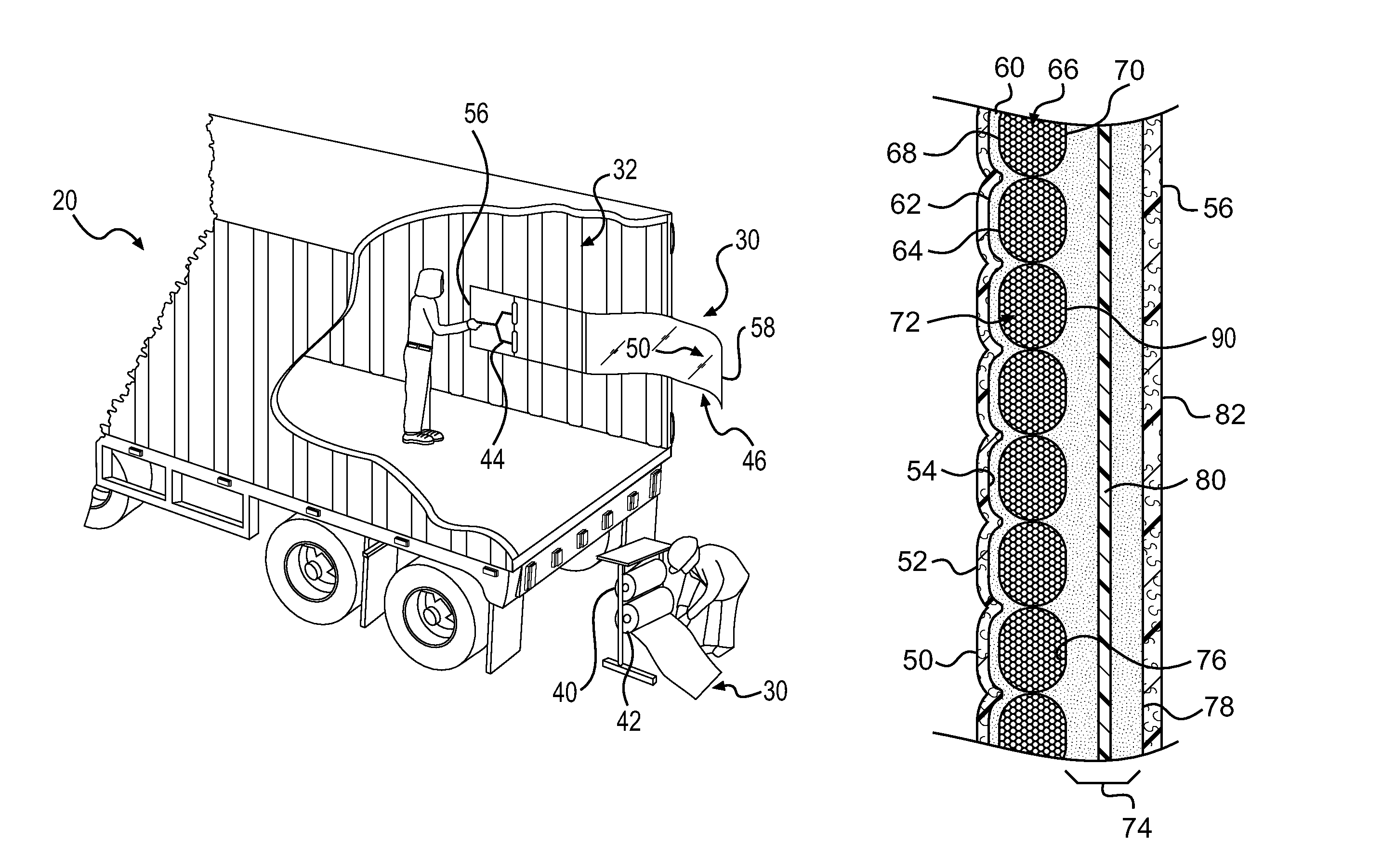
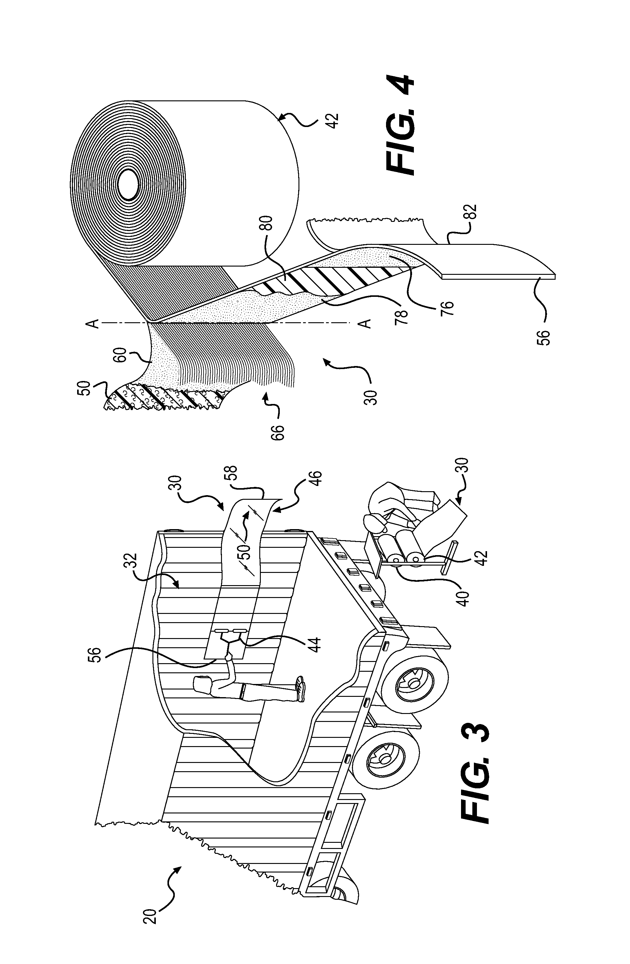
[0037]FIG. 2 is an axonometric view, partially broken away, and discloses another operating context of the invention. In this view an intermodal or cargo container 20 is shown mounted upon a trailer 22 which is operably towed by a tractor 24 for land transport. Containers such as these are also often mounted on railway flat cars either directly or as attached to truck trailers 22.

[0038]A partially cut away rear corner port...


PUM


Abstract

A cargo restraint system with enhanced filament characteristics wherein the restraint system includes laminated load restraining strips with a layer of reinforcement material comprising a plurality of substantially parallel bundles of filaments and wherein the layer of reinforcement filaments each have a break strength of approximately fifteen point nine (15.9 grams to approximately twenty point seven (20.7) grams.

Description

RELATED PATENTS[0001]This application relates to U.S. Pat. No. 6,089,802 entitled “Cargo Restraint System for a Transport Container” issued on Jul. 18, 2000; U.S. Pat. No. 6,227,779 entitled “Cargo Restraint Method for a Transport Container” issued on May 8, 2001; U.S. Pat. No. 6,607,337 entitled “Cargo Restraint System” issued on Aug. 19, 2003; U.S. Pat. No. 6,896,459 issued on May 24, 2005; U.S. Pat. No. 6,923,609 issued on Aug. 2, 2005; U.S. Pat. No. 7,018,151 issued on Mar. 28, 2006; U.S. Pat. No. 7,066,698 issued on Jun. 27, 2006; U.S. Pat. No. 7,290,969 issued on Nov. 6, 2007; U.S. Pat. No. 7,329,074 issued on Feb. 12, 2008 and United States Bullock application for patent entitled “Cargo Restraint Method and System With Enhanced Shear Strength” Ser. No. 12 / 481,345 filed on Jun. 9, 2009 and United States Bullock application for patent entitled “Cargo Restraint System With Enhanced Peel Strength” Ser. No. 12 / 486,897 filed on Jun. 18, 2009. All of the above are of common inventor...

Claims


Application Information

Patent Timeline
Patent Type & Authority Patents(United States)
IPC IPC(8): B60P7/08
CPCB60P7/0823
Inventor BULLOCK, MATTHEW
Owner MBULL HLDG LLC
Why Eureka
Try Eureka