X-ray convergence element and X-ray irradiation device

a technology of x-ray irradiation element and x-ray irradiation device, which is applied in the direction of nuclear engineering, diaphragm/collimeter, and diffraction/refraction/reflection. it is difficult to ensure a working distance (wd) from the opening end on the exit side to a specimen, and the diffraction of x-rays cannot be sufficiently analyzed. it is easy to arrange and simple to achieve

Active Publication Date: 2013-04-09
HORIBA LTD +1
View PDF13 Cites 1 Cited by
  • Summary
  • Abstract
  • Description
  • Claims
  • Application Information

AI Technical Summary

Benefits of technology

[0007]The present invention is made in view of the conditions described hereinabove, and provides an X-ray convergence element and an X-ray irradiation device including the X-ray convergence element. The X-ray convergence element includes a tubular body in which a diameter of an entrance-side opening end thereof is greater than that of the exit-side opening end, and an X-ray blocking member having a diameter that is approximately the same as the diameter of the exit-side opening end, the center of which being arranged on the center axis of the tubular body. Therefore, a working distance from the exit-side opening end to the specimen can be extended, and an analysis of the specimen with rough surface, a fluorescent X-ray analysis, and an X-ray diffraction analysis can be performed regardless of a size of the specimen.
[0039]According to the seventh and ninth aspects of the invention, the fixing members are spaced from each other with a predetermined distance in the circumferential direction of the tubular body, and are stick-like bodies arranged approximately parallel to each other in the axial direction of the tubular body. Therefore, the center of the X-ray blocking member is easily arranged on the canter axis of the tubular body.

Problems solved by technology

Although the diameter of the other opening end on the exit side is reduced, the distance to converge the exiting X-rays is shortened to make it difficult to sufficiently ensure a working distance (WD) from the opening end on the exit side to a specimen (e.g., approximately 0.1 mm).
Therefore, there arise problems in which a sample (specimen) with rough surface cannot be analyzed, a takeoff angle of fluorescent X-rays emitted from the sample cannot be ensured, diffraction of X-rays cannot be sufficiently analyzed, because the sample cannot be rotated or inclined.

Method used


Image

  • X-ray convergence element and X-ray irradiation device
  • X-ray convergence element and X-ray irradiation device
  • X-ray convergence element and X-ray irradiation device

Examples


embodiment 1

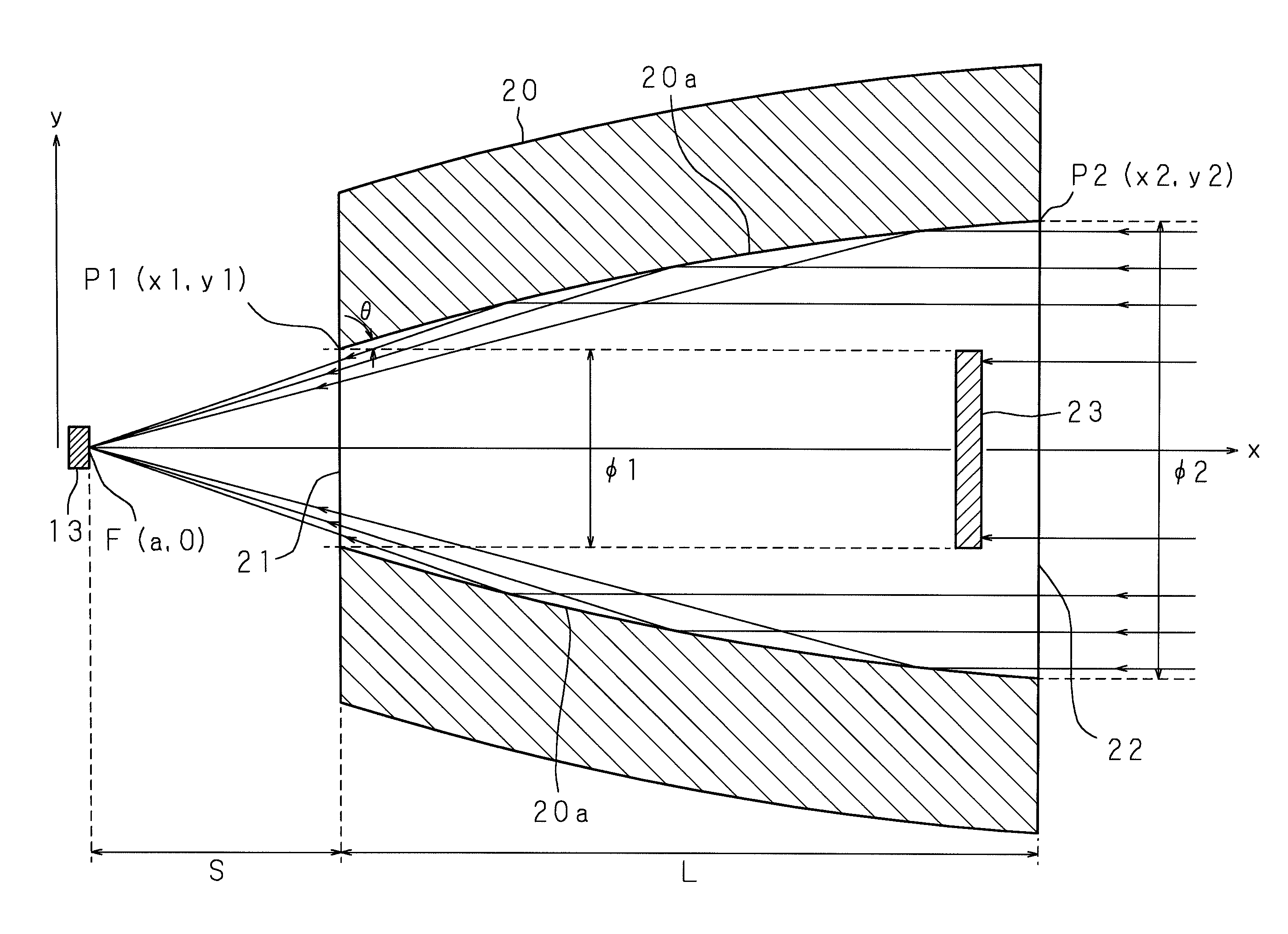
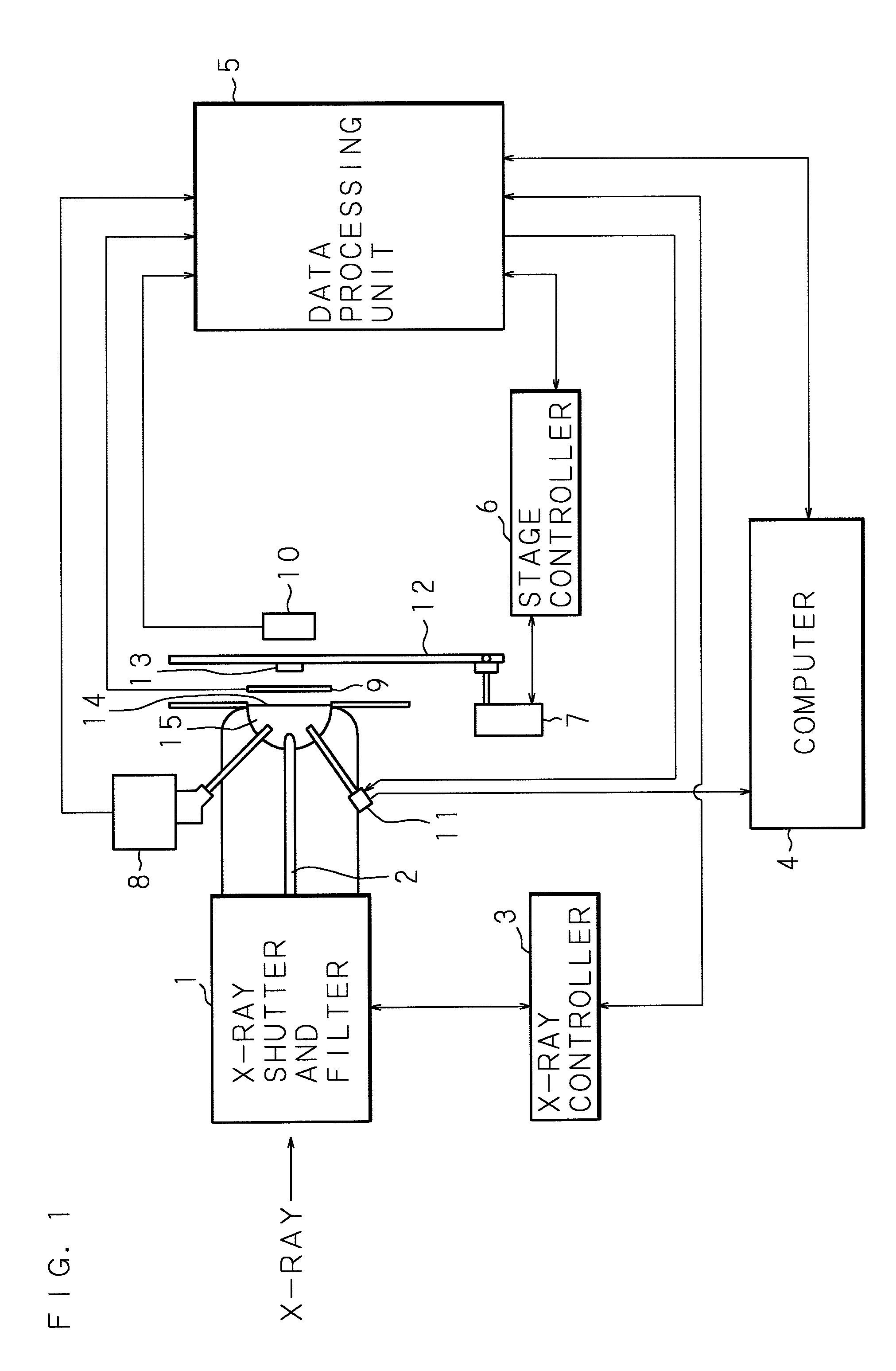
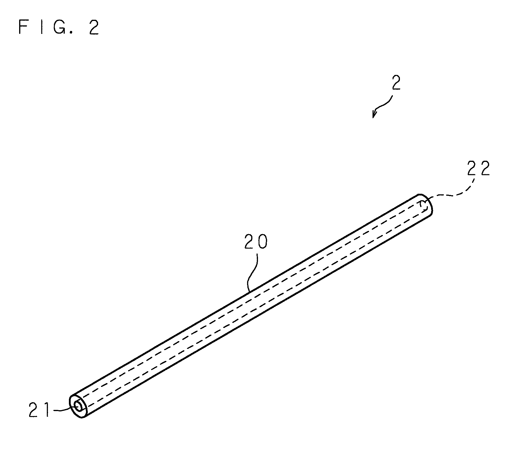
[0050]Hereinafter, the present invention will be described based on the appending drawings illustrating embodiments thereof. FIG. 1 is a block diagram showing a configuration of an X-ray analyzing device including an X-ray convergence element according to the present invention. In this figure, the reference numeral 1 indicates an X-ray shutter and filter for controlling ON / OFF of X-rays and an output intensity of X-rays. An X-ray convergence element 2 is attached to the X-ray shutter and filter 1. A parallel X-ray beam exiting from the X-ray shutter and filter 1 enters into the X-ray convergence element 2, the X-ray convergence element 2 totally reflects the entered X-rays on an inner surface of the X-ray convergence element 2 to converge the X-rays. Then, a diameter of the beam is narrowed by, for example 1 μm order, while leading the X-rays to an opening 15 provided in proximity to a sample stage 12.

[0051]In this embodiment, the opening 15 is a space closed with an X-ray transmitt...

embodiment 2

[0076]FIGS. 5A and 5B are views showing another shape of the X-ray blocking member. FIG. 5A shows a front view of the X-ray blocking member 24, and FIG. 5B shows a longitudinal cross-sectional view thereof. A difference from Embodiment 1 is that the diameter of the X-ray blocking member 24 is narrowed toward the X-ray entering side.

[0077]The X-ray blocking member 24 is provided with three supporting members 243 for supporting the X-ray blocking member 24 so as to extend from an annular member 242 having approximately the same diameter as the diameter of the entrance-side opening end 22 (outer diameter of the capillary 20) toward the center of the X-ray blocking member 24. The annular member 242 is fixed to the capillary 20. In this case, when the entered X-rays from the entrance-side opening end 22 are reflected on a side surface of the X-ray blocking member 24 approximately in the axial direction, traveling directions of the entered X-rays are significantly changed, and thereby pre...

embodiment 3

[0078]FIGS. 6A and 6B are views showing still another shape of the X-ray blocking member. FIG. 6A shows a front view of the X-ray blocking member 25, and FIG. 6B shows a longitudinal cross-sectional view thereof. A difference from Embodiment 1 is that an X-ray incident surface of the X-ray blocking member 25 forms a part of a spherical surface.

[0079]The X-ray blocking member 25 is provided with three supporting members 253 for supporting the X-ray blocking member 25 so as to extend from an annular member 252 having approximately the same diameter as the diameter of the entrance-side opening end 22 (outer diameter of the capillary 20) toward the center of the X-ray blocking member 24. The annular member 252 is fixed to the capillary 20. In this case, the X-rays entering from the entrance-side opening end 22 can be blocked without being reflected on the side surface of the X-ray blocking member 25 approximately in the axial direction. Therefore, the unnecessary scattered X-rays reflec...


PUM


Abstract

An X-ray convergence element and an X-ray irradiation device including the X-ray convergence element are provided. The X-ray convergence element can extend a working distance from an exit-side opening end thereof to a specimen, and can perform analysis of the specimen with rough surface, a fluorescent X-ray analysis, and a X-ray diffraction analysis, regardless of a size of the specimen. An X-ray blocking member 23 is provided with three supporting members 233 for supporting the X-ray blocking member 23, which extend from an annular member 232 having approximately the same diameter as a diameter of an entrance-side opening end (outer diameter of a capillary 20) toward the center of the X-ray blocking member 23 to fix the annular member 232 to the capillary 20. The annular member 232, the supporting members 233, and the X-ray blocking member 23 are integrally formed of a metal that shields X-rays, such as tantalum, tungsten, or molybdenum. A dimension of the X-ray blocking member 23 in the axial direction (thickness) is set to be sufficient for blocking X-rays.

Description

RELATED APPLICATIONS[0001]This application is a National Phase Application of PCT International Application No. PCT / JP2007 / 052209, which has an International filing date of Feb. 8, 2007, and which designated the United States of America.TECHNICAL FIELD[0002]The present invention relates to an X-ray convergence element including a tubular body, for reflecting X-rays entered into the tubular body, and for converging the reflected X-rays, and to an X-ray irradiation device including the X-ray convergence element.BACKGROUND ART[0003]For various purposes, such as research and development including development of materials or examination of living bodies, quality management including foreign object analyses or defect analyses, or the like, an X-ray analyzing device is utilized for irradiating X-rays onto a sample, detecting fluorescent X-rays emitted from the sample, transmitted X-rays through the sample, diffracted X-rays, or the like, and analyzing an internal composition or crystal str...

Claims


Application Information

Patent Timeline
Patent Type & Authority Patents(United States)
IPC IPC(8): G21K1/06
CPCG21K1/06G21K2201/064
Inventor NAKAZAWA, HIROMOTOYOSHIKAWA, HIDEKIVLAICU, AUREL-MIHAIOBORI, KENICHIKOMATANI, SHINTAROOHZAWA, SUMITO
Owner HORIBA LTD
Why Eureka
Try Eureka