Perpendicular magnetic recording medium and method of manufacturing the same

a technology of magnetic recording medium and perpendicular magnetic layer, which is applied in the field of perpendicular magnetic recording medium, can solve the problems of difficult to achieve further improvement of the crystal orientation of the underlayer, and the soft magnetic layer may not be protected sufficiently, so as to improve the crystal orientation, improve the snr, and reduce the roughness of the boundary surface

Active Publication Date: 2013-04-30
WESTERN DIGITAL TECH INC
View PDF6 Cites 71 Cited by
  • Summary
  • Abstract
  • Description
  • Claims
  • Application Information

AI Technical Summary

Benefits of technology

[0012]The inventors have examined solutions for further improving the SNR and have found that they have to focus on states of boundary surfaces of a non-magnetic layer and a plurality of layers formed on the non-magnetic layer. Specifically, the inventors have considered that the crystallinity of the magnetic recording layer becomes disordered when the boundary surfaces are roughened and that the SNR can be improved by reduction of the roughness of those boundary surfaces.
[0057]According to the present invention, there is provided a perpendicular magnetic recording medium capable of improving the crystal orientation by reduction of the roughness of a boundary surface between a non-magnetic layer and a soft magnetic layer, of improving the SNR by improvement of atomic distance matching between the non-magnetic layer and an underlayer, and of further increasing the recording density. There is also provided a method of manufacturing such a perpendicular magnetic recording medium.

Problems solved by technology

Accordingly, it is difficult to achieve further improvement of the crystal orientation of an underlayer and dramatic improvement of the SNR with this technology.
If the ratio of the aforementioned element(s) or compound thereof is less than 40 atomic %, it is undesirable because the Ni compound cannot sufficiently be formed into an amorphous phase.
If the ratio is higher than 60 atomic %, it is undesirable because the amount of Ni, which is a base of growth of crystal grains of the second non-magnetic layer formed on the first non-magnetic layer, unfavorably becomes insufficient.
If the ratio is less than 3 atomic %, it is undesirable because the Ni compound unfavorably shows a ferromagnetic property.
If the ratio is higher than 8 atomic %, it is undesirable because the orientation of Ni is unfavorably deteriorated.
If the thickness of the first non-magnetic layer is smaller than 1 nm, the soft magnetic layer may not be protected sufficiently.

Method used


Image

  • Perpendicular magnetic recording medium and method of manufacturing the same
  • Perpendicular magnetic recording medium and method of manufacturing the same
  • Perpendicular magnetic recording medium and method of manufacturing the same

Examples


first embodiment

Perpendicular Magnetic Recording Medium

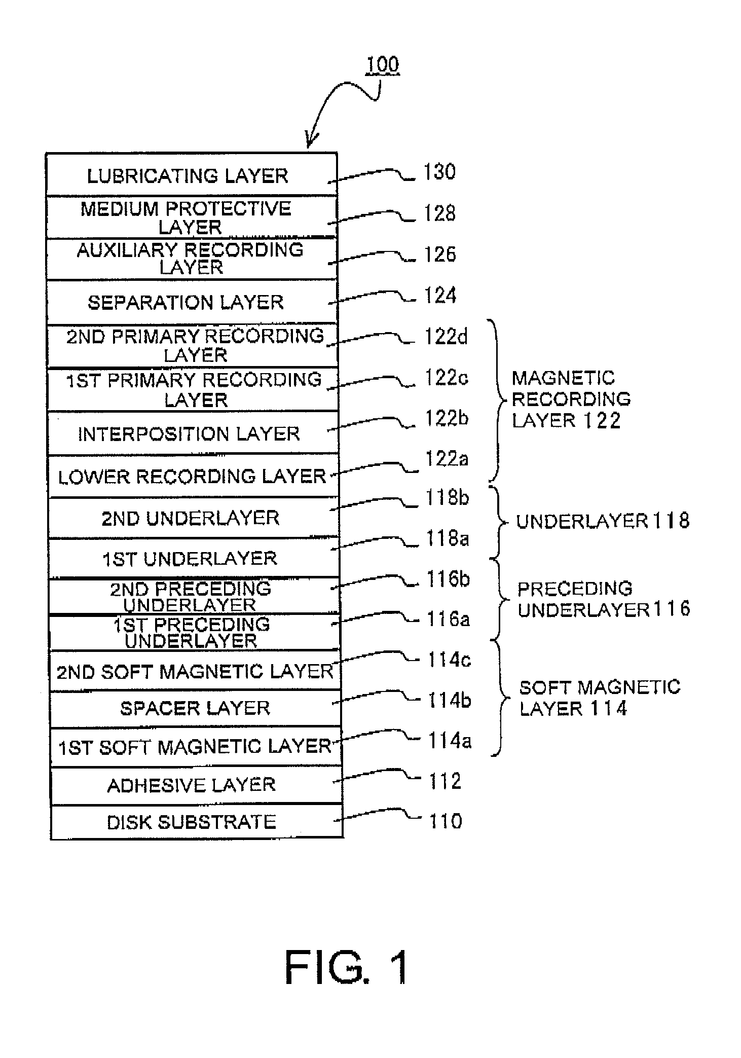
[0067]FIG. 1 is a diagram explanatory of a configuration of a perpendicular magnetic recording medium 100 according to a first embodiment. The perpendicular magnetic recording medium 100 shown in FIG. 1 has a disk substrate 110, an adhesive layer 112, a first soft magnetic layer 1148, a spacer layer 114b, a second soft magnetic layer 114c, a first preceding underlayer 116a (first non-magnetic layer), a second preceding underlayer 116b (second non-magnetic layer), a first underlayer 118a, a second underlayer 118b, a lower recording layer 122a, an interposition layer 122b, a first primary recording layer 122c, a second primary recording layer 122d, a separation layer 124, an auxiliary recording layer 126, a medium protective layer 128, and a lubricating layer 130. The first soft magnetic layer 114a, the spacer layer 114b, and the second soft magnetic layer 114c jointly form a soft magnetic layer 114. The first preceding underlayer 116a and the se...

second embodiment

[0124]The inventors have found that a boundary surface between a non-magnetic layer and a soft magnetic layer tends to be roughened if a bias voltage is applied to a substrate when the non-magnetic layer is formed on the soft magnetic layer (on sputtering). Therefore, the inventors considered forming a non-magnetic layer without application of a bias voltage. However, application of a bias voltage during the formation of the non-magnetic layer is performed for improvement of magnetostatic characteristics (particularly the magnetic coercive force (Hc)). Therefore, characteristics are considerably deteriorated if no bias voltage is applied. Accordingly, application of a bias voltage is required during the formation of the non-magnetic layer.

[0125]The inventors have continuously studied and have considered interposing a layer between a non-magnetic layer and a soft magnetic layer formed below the non-magnetic layer for protecting the soft magnetic layer. The inventors have considered t...

third embodiment

[0148]The inventors have found that a boundary surface between a non-magnetic layer and a soft magnetic layer tends to be roughened if a bias voltage is applied to a substrate when the non-magnetic layer is formed on the soft magnetic layer (on sputtering). Therefore, the inventors considered forming a non-magnetic layer without application of a bias voltage. However, application of a bias voltage during the formation of the non-magnetic layer is performed for improvement of magnetostatic characteristics. Therefore, characteristics are considerably deteriorated if no bias voltage is applied. Accordingly, application of a bias voltage is required during the formation of the non-magnetic layer.

[0149]The inventors have continuously studied and have found that, when a layer is interposed between a non-magnetic layer and a soft magnetic layer formed below the non-magnetic layer under certain conditions, adverse influence on the soft magnetic layer from the non-magnetic layer can be elimi...


PUM

PropertyMeasurementUnit
surface roughnessaaaaaaaaaa
Vickers hardnessaaaaaaaaaa

Abstract

A perpendicular magnetic recording medium comprises a magnetic recording layer that records a signal, an underlayer formed of Ru or Ru compound below the magnetic recording layer, a non-magnetic layer formed of a non-magnetic material below the underlayer to control crystal orientation of the underlayer, a soft magnetic layer provided below the non-magnetic layer, and a substrate on which the magnetic recording layer, the underlayer, the non-magnetic layer, and the soft magnetic layer are formed. The non-magnetic layer comprises a first non-magnetic layer formed above the soft magnetic layer and a second non-magnetic layer formed above the first non-magnetic layer. The first non-magnetic layer is formed of amorphous Ni compound while the second non-magnetic layer is formed of crystalline Ni or crystalline Ni compound.

Description

[0001]This application is based upon and claims the benefit of priority from Japanese Patent Application No. 2009-083611, filed on Mar. 30, 2009, Japanese Patent Application No. 2009-083612, filed on Mar. 30, 2009, Japanese Patent Application No. 2009-087760, filed on Mar. 31, 2009, and Japanese Patent Application No. 2009-087761, filed on Mar. 31, 2009, the disclosures of which are incorporated herein in their entirety by reference.BACKGROUND[0002]1. Field of the Invention[0003]The present invention relates to a perpendicular magnetic recording medium mounted on a perpendicular magnetic recording type hard disk drive (HDD) or the like and a method of manufacturing such a medium.[0004]2. Description of the Related Art[0005]Various information recording techniques have been developed along with recent increase of capacity in information processing. Particularly, the areal recording density of hard disk drives (HDDs) using a magnetic recording technique has continued to increase at an...

Claims


Application Information

Patent Timeline
Patent Type & Authority Patents(United States)
IPC IPC(8): G11B5/66
CPCG11B5/65G11B5/667G11B5/7325G11B5/82G11B5/8404G11B5/737
Inventor ONOUE, TAKAHIROSATO, TOKICHIROKAJIWARA, TAKENORI
Owner WESTERN DIGITAL TECH INC
Why Eureka
Try Eureka