

Mechanical seal device, sliding element, and method of production thereof
a mechanical seal and sliding element technology, applied in mechanical devices, machines/engines, transportation and packaging, etc., can solve the problems of remarkably worn, low effect of above atmosphere, and wear, and achieve superior corrosion resistance, reduce the generation of wear powder, and prevent the effect of sliding surface wear
- Summary
- Abstract
- Description
- Claims
- Application Information
AI Technical Summary
Benefits of technology
Problems solved by technology
Method used
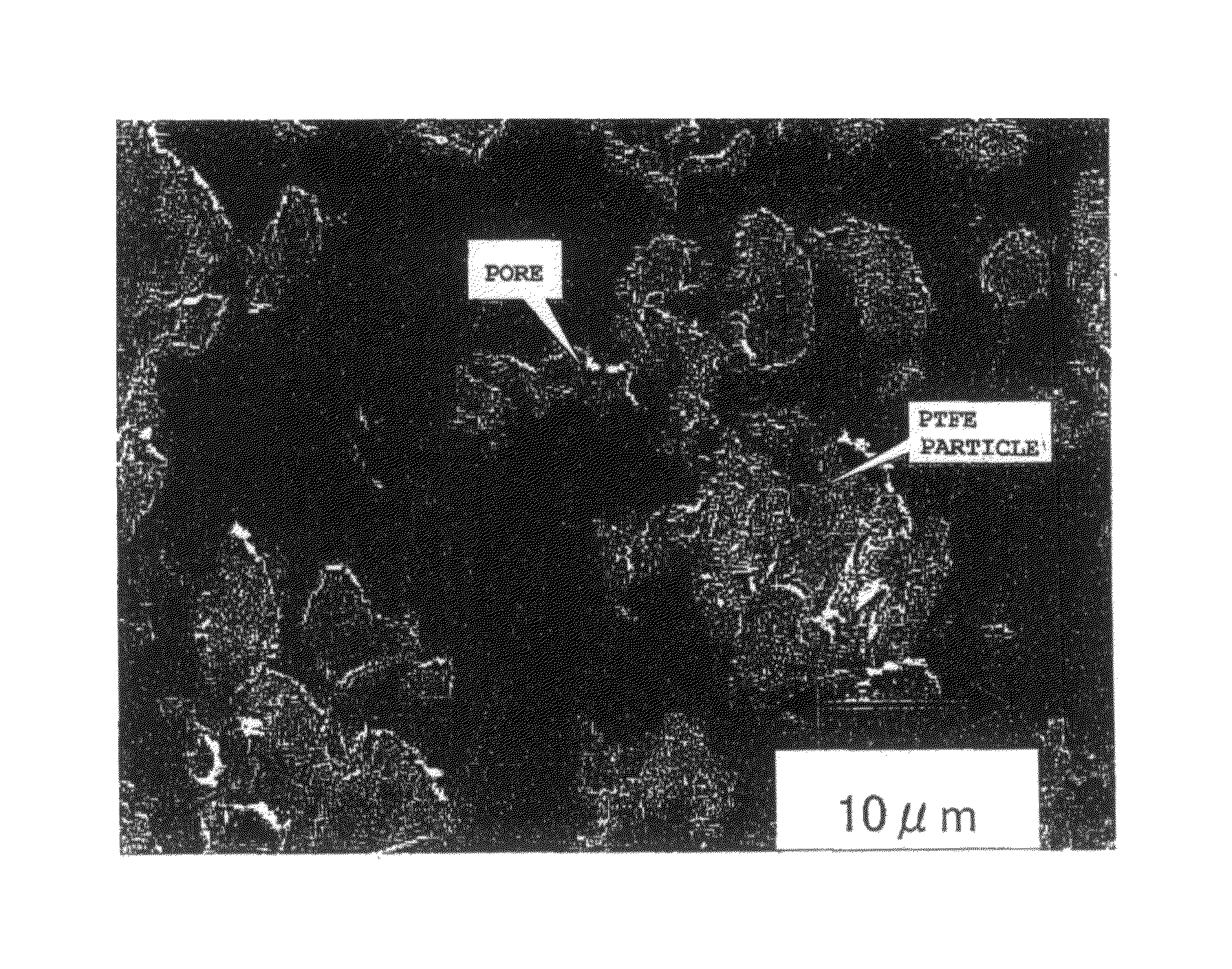
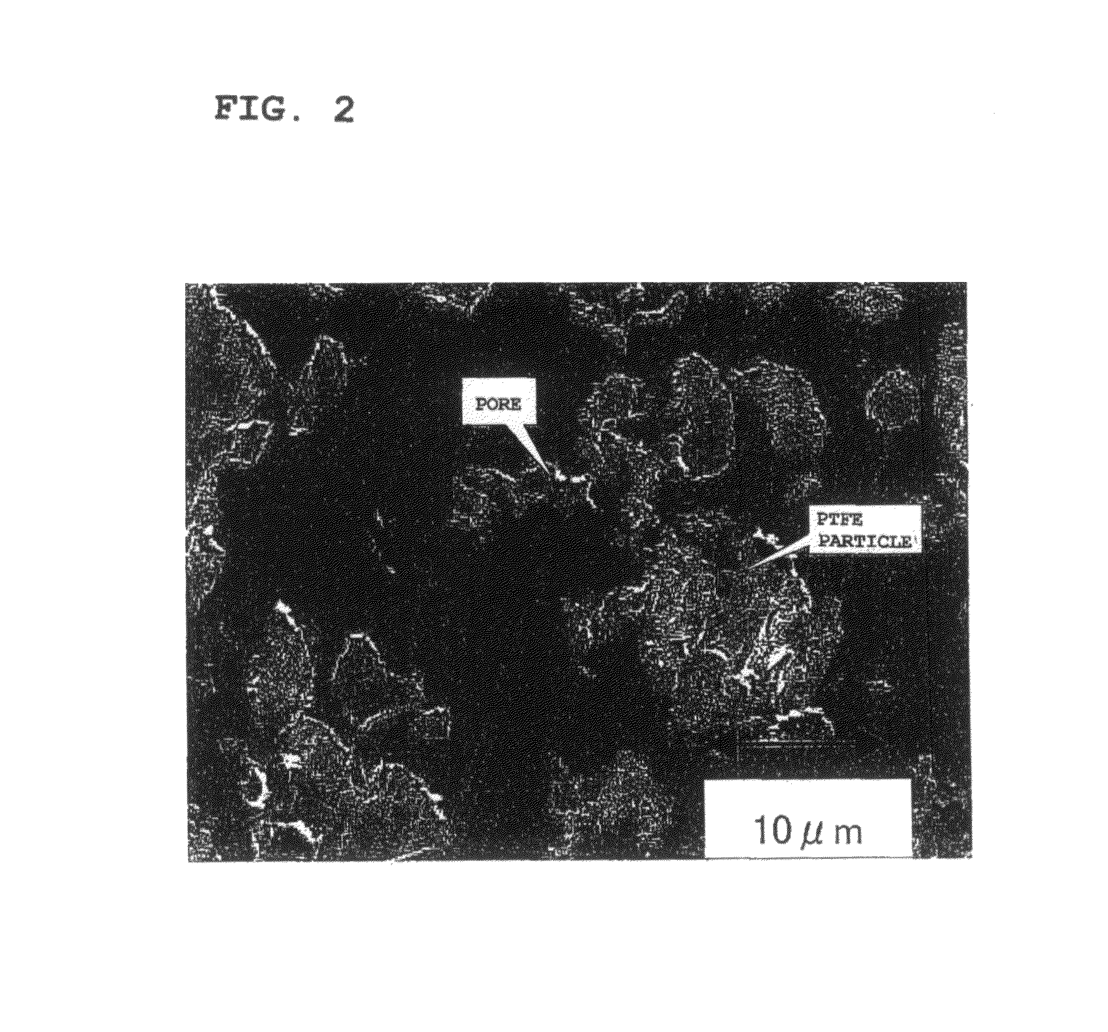
Image

Examples
example 1
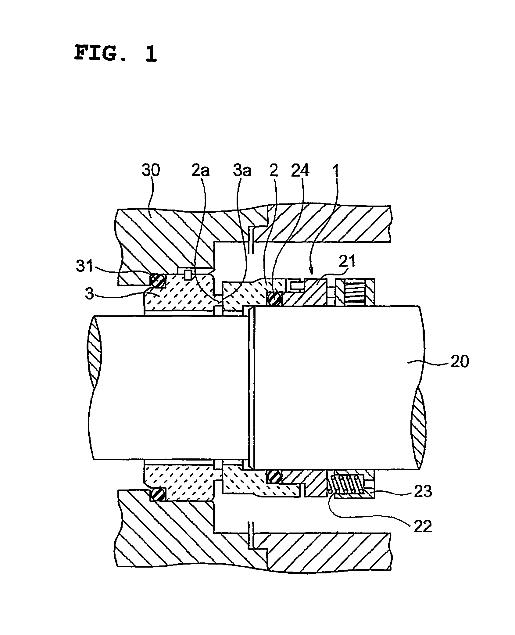
[0073]As the substrate, silicon carbide (specific gravity 3.05 or more) was used to prepare a sintered body comprised of a seal ring 2 on rotating side and floating seat 3 on stationary side shown in FIG. 1. In this example, the sliding surface 2a of the seal ring 2 on rotating side had an inside diameter of φ56.5 mm and an outside diameter of φ75 mm (size of seal ring 2 itself being an inside diameter of φ56. 5 mm, an outside diameter of φ77 mm, and a height of 26.5 mm), while the sliding surface 3a of the floating seat 3 on stationary side had an inside diameter of φ58.6 mm and an outside diameter of φ66.1 mm (size of floating seat 3 itself being an inside diameter of φ56 mm, an outside diameter of φ81 mm, and a height of 27 mm).
[0074]Further, the respective sliding surfaces 2a and 3a of the seal ring 2 and floating seat 3 were grinded and lapped to obtain a surface roughness Ra of 0.05 μm. Next, the grinded and lapped sliding surfaces 2a and 3a were roughened using 9 μm diamond p...
example 2
[0086]Except for changing the polyamide-imide resin to a polyimide resin, the same procedure was followed as in Example 1 to produce the seal ring 2 and floating seat 3 and to conduct a rotational sliding test. The results are shown in Table 2.
examples 3 to 6
[0091]Except for changing a part of the
[0092]polytetrafluoroethylene resin contained in the resin layer to graphite powder as shown in Table 3, the same procedure was followed as in Example 1 to produce the seal ring 2 and floating seat 3 and to conduct a rotational sliding test. The results are shown in Table 3.
[0093]
TABLE 3Resin layer [wt %]HeatAmount of wear [μm]RingingGraphitetreatment temp.Stationary (SlidingPTFEPAIpowder[° C.]Oil ingredientRotating sidesidenoise)Ex. 335605340DEMNUM S-2000.20NoneEx. 4256015340DEMNUM S-2000.40NoneEx. 5156025340DEMNUM S-2000.60.1NoneEx. 656035340DEMNUM S-2000.70.2None
[0094]Evaluation 3
[0095]From Table 3, it can be confirmed that even when introducing graphite powder in the resin layers, the effect of the present invention can be obtained. Note that from Table 3, if the content of the polytetrafluoroethylene resin decreases, it can be confirmed that the amount of wear tends to increase somewhat.
PUM
| Property | Measurement | Unit |
|---|---|---|
| thickness | aaaaa | aaaaa |
| melting point | aaaaa | aaaaa |
| porosity | aaaaa | aaaaa |
Abstract
Description
Claims
Application Information