Power conversion apparatus

a technology of power conversion apparatus and power converter, which is applied in the direction of dc-dc conversion, power electronics conversion, transportation and packaging, etc., can solve the problems of increasing the loss of dc/dc converter section, complicated control, etc., and achieves the improvement of the availability of parts, the effect of reducing the design period of hardware and reducing the cost of parts

Active Publication Date: 2013-05-28
MITSUBISHI ELECTRIC CORP
View PDF10 Cites 7 Cited by
  • Summary
  • Abstract
  • Description
  • Claims
  • Application Information

AI Technical Summary

Benefits of technology

[0007]in which a target value of an output voltage of the AC / DC converter section is generated in accordance with output voltage and current values to reduce a power loss and noise of the power conversion apparatus and to eliminate a large current-limiting circuit for a reduction in size, and
[0010]According to the present invention, the operational input voltage range of the power conversion apparatus may be widened and the maximum efficiency value comparable to that in the case where the operational input voltage range is not widened may be obtained by changing software but not hardware. The hardware is not changed, and hence a design period of the hardware may be significantly shortened and common parts are easily used for power conversion apparatus having different input voltage ranges. Therefore, the improvement of availability of parts and the reduction in part cost are expected because of the advantages of scale.

Problems solved by technology

However, there is a problem that control is complicated and a loss of the DC / DC converter section increases.

Method used


Image

  • Power conversion apparatus
  • Power conversion apparatus
  • Power conversion apparatus

Examples


first embodiment

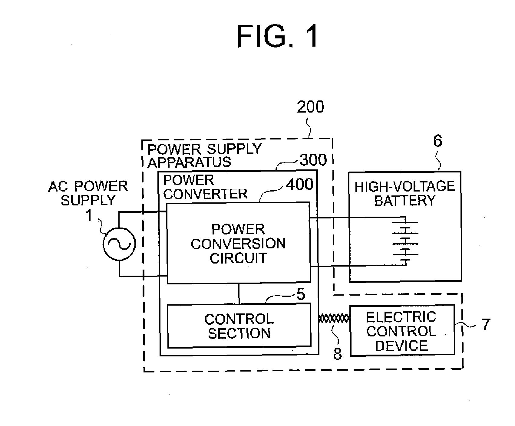
[0034]FIG. 1 is a block structural diagram illustrating a power conversion apparatus according to the present invention, serving as a power supply apparatus. FIG. 1 illustrates an example in which the power conversion apparatus is used as a power supply apparatus 200 to which an AC voltage source 1 (hereinafter, referred to simply as AC power supply 1) is connected on an input side thereof to charge a high-voltage battery 6 connected to an output side thereof. The power supply apparatus (power conversion apparatus) 200 includes a power converter 300 and an electric control device 7. The power converter 300 includes a power conversion circuit 400 and a control section 5.

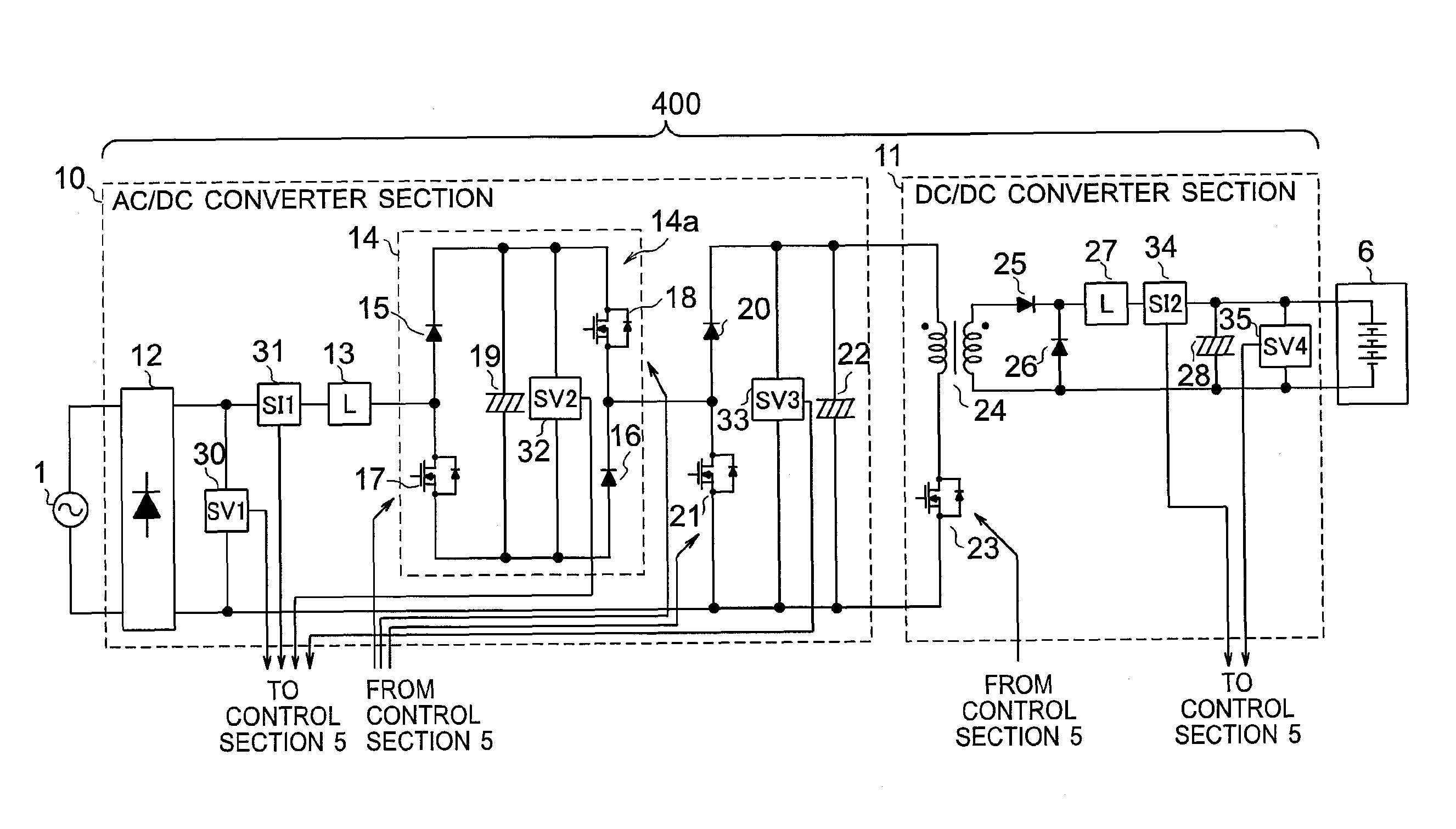
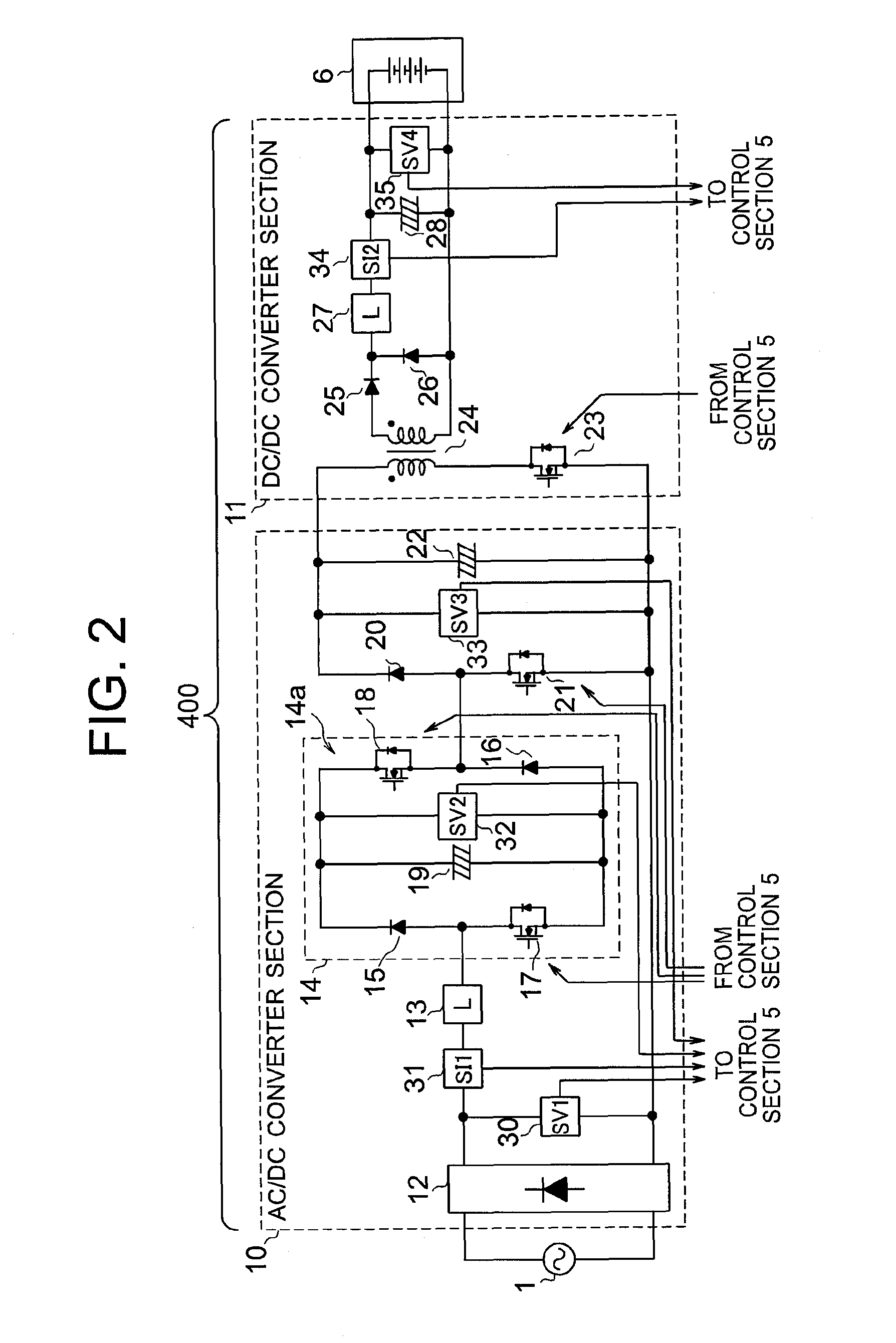
[0035]The power conversion circuit 400 is a circuit for performing power conversion by switching, which receives input power from the AC power supply 1 and charges the high-voltage battery 6 connected to the output stage. Detection circuits (see FIG. 2) attached to predetermined portions of the power conversion circui...

second embodiment

[0102]FIG. 14 is a schematic structural diagram illustrating an example of the internal structure of the power conversion circuit 400 illustrated in FIG. 1 in a second embodiment of the present invention. The entire structure of the power conversion apparatus is the same as the structure illustrated in FIG. 1. The structure illustrated in FIG. 14 is different from the structure illustrated in FIG. 2 (first embodiment) in that the output current detection circuit 34 is omitted. The control of the control section 5 for causing the output current to follow the target current value Iout* in the structure illustrated in FIG. 14 is described in detail below.

[0103]Symbols are defined as follows.

[0104]Pin: input power from AC power supply 1

[0105]Iout*: control target current value of output current Iout

[0106]FIG. 15 is a control block diagram illustrating control of the forward converter switch 23 which is performed by the DC / DC converter control means 5a illustrated in FIG. 3. Firstly, th...


PUM


Abstract

In order to widen an operational input voltage range of a power conversion apparatus and obtain a maximum efficiency value comparable to that in a case where the operational input voltage range is not widened by changing software but not hardware, provided is a power conversion apparatus, in which a control section (5) controls a current input to an inverter circuit (14) to cause a DC output voltage from an AC / DC converter section (10) which is a voltage across a smoothing capacitor (22) to follow a target voltage and to cause an input power factor from an AC power supply (1) to approach one, to thereby maintain a DC voltage from a single-phase inverter (14a), and adjusts the target voltage for the DC output voltage from the AC / DC converter section (10) in accordance with a voltage of the AC power supply (1).

Description

BACKGROUND OF THE INVENTION[0001]1. Field of the Invention[0002]The present invention relates to a power conversion apparatus which includes a high-power factor converter for converting an alternating current (AC) voltage into a direct current (DC) voltage and an insulated DC / DC converter provided in a subsequent stage thereof.[0003]2. Description of the Related Art[0004]A conventional power conversion apparatus includes an AC / DC converter section for controlling a power factor of a commercial AC power supply to perform AC / DC conversion and a DC / DC converter section which is provided in a subsequent stage of the AC / DC converter section and insulated by a transformer (see, for example, Japanese Patent Application Laid-open No. 2008-118727).[0005]For example, in the conventional power conversion apparatus described above, in order to charge a DC power supply 1 and a DC power supply 2 which are insulated from each other, a primary-side switching circuit of the DC / DC converter section i...

Claims


Application Information

Patent Timeline
Patent Type & Authority Patents(United States)
IPC IPC(8): H02J7/04H02J7/00
CPCH02M1/4258Y02B70/126H02M1/4225H02M3/335Y02B70/10H02M1/007
Inventor AWANE, KAZUTOSHIYAMADA, MASAKIKANEYAMA, TAKASHIKONDO, RYOTA
Owner MITSUBISHI ELECTRIC CORP
Why Eureka
Try Eureka