Method and apparatus for incineration of combustible waste

a technology of combustible waste and incineration method, which is applied in the direction of lighting and heating apparatus, combustion types, greenhouse gas reduction, etc., can solve the problems of varying the amount of material retention time, negatively affecting the kiln performance of cement making operation, and not necessarily adaptable to combustible waste of different types at the same time, so as to maximize the firing of alternate fuels and short material retention time

Inactive Publication Date: 2013-07-02
F L SMIDTH & CO AS
View PDF5 Cites 12 Cited by
  • Summary
  • Abstract
  • Description
  • Claims
  • Application Information

AI Technical Summary

Benefits of technology

[0007]The invention comprises the novel combination of two dissimilar types of combustion chambers in a manner that overcomes the process disadvantages of each chamber. In particular, the invention comprises the use of a first, down draft, combustion chamber employing a very short material retention time upstream from and in series with a second combustion chamber suitable for combusting large solid alternate fuels. Said second chamber is characterized by (a) having a comparatively long material retention time; (b) having a supporting surface for the waste and (c) transporting the waste during incineration through the compartment to its outlet in a circular path. The combination of two completely different combustion chambers in series serves to thereby maximize the firing of alternate fuels in the cement making process. For example, liquid fuels, finely divided solid fuels or shredded tires, can be fired in the first combustion chamber while burning whole tires in the second combustion chamber.

Problems solved by technology

However, the compartment characterized above is not necessarily adaptable for combusting different types of waste simultaneously, each of which may require varying amounts of material retention time.
These combustion chambers, employed upstream from a calciner, pose problems if there is incomplete combustion, which can happen for example if they are used to combust larger sized waste fuels or a single alternative fuel source that has varying sized particles (for instance, shredded tires having widely varying sized particles) in that there will be a fall out of larger unburned particles into the kiln inlet.
Such particles when burned at the kiln inlet will promote reduction conditions in the kiln which will negatively affect kiln performance in a cement making operation.

Method used


Image

  • Method and apparatus for incineration of combustible waste
  • Method and apparatus for incineration of combustible waste
  • Method and apparatus for incineration of combustible waste

Examples


Embodiment Construction

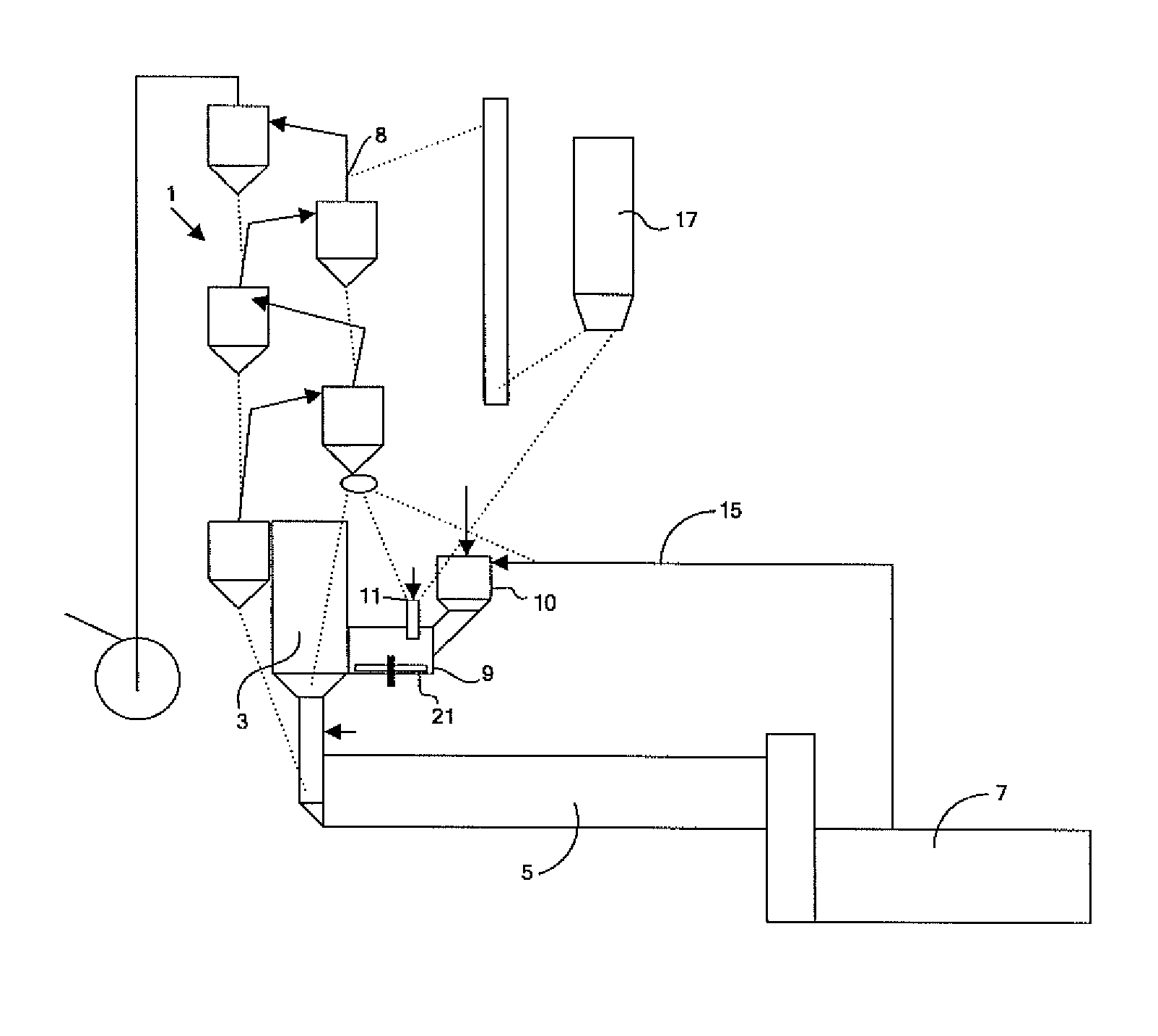
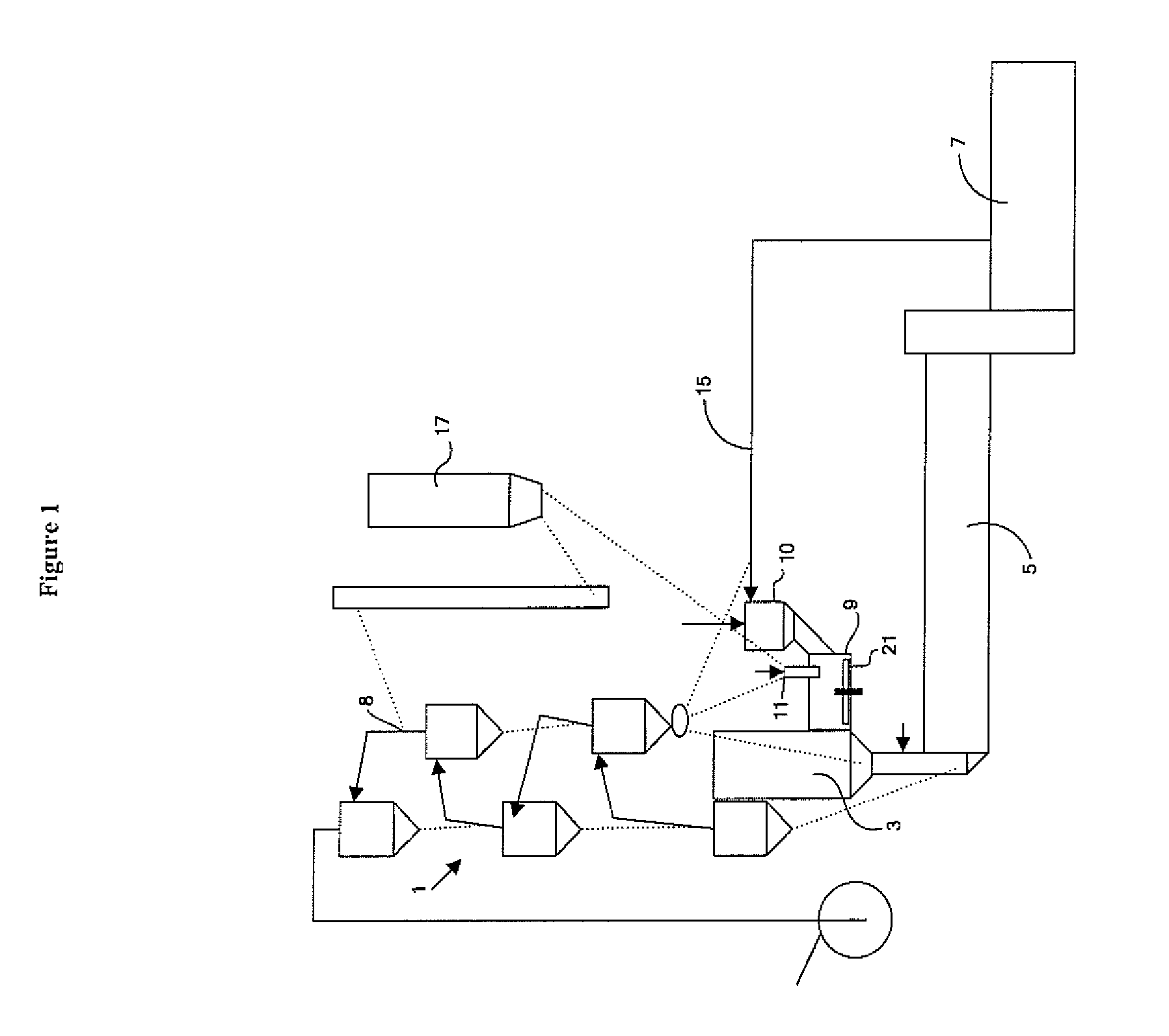
[0012]In FIG. 1 is seen a plant for manufacturing cement clinker. The plant comprises a cyclone preheater 1 with calciner 3, a rotary kiln 5, a clinker cooler 7, a first combustion chamber 10 for incineration of waste which is introduced via an opening in the chamber and a second combustion chamber 9 for incineration of waste which is introduced via an opening in the chamber, with the second chamber being located between the calciner 3 and the first chamber 10. During operation the cement raw meal is directed from a raw meal store 17 to the raw meal inlet 8 of the preheater 1. From there the raw meal flows towards the rotary kiln 5 through the cyclones of the preheater 1 and the calciner 3 in counterflow to hot exhaust gases from the rotary kiln 5, thereby causing the raw meal to be heated and calcined. In the rotary kiln 5 the calcined raw meal is burned into cement clinker which is cooled in the subsequent clinker cooler 7 by means of atmospheric air. Some of the air thus heated i...


PUM

PropertyMeasurementUnit
retention timeaaaaaaaaaa
sizeaaaaaaaaaa
retention timeaaaaaaaaaa

Abstract

A method and apparatus for incinerating different types of combustible waste in a cement manufacturing process. Two combustion chambers for incinerating waste are arranged in series, with first combustion chamber being a down draft chamber in which there is a downward flow of combustion gas and waste fuel to a waste and gas outlet. The second chamber is adaptable to support waste on a supporting surface incorporated in the compartment, wherein the waste is transported through the compartment from a waste inlet to a waste outlet along a circular path.

Description

BACKGROUND OF THE INVENTION[0001]The present invention relates to a method for incineration of combustible waste that provides heat utilized in the manufacture of cement clinker where cement raw meal is preheated and calcined in a preheater system with a calciner, burned into clinker in a kiln and cooled in a subsequent clinker cooler. More specifically the invention involves the method of using two separate combustion chambers in series for maximizing the firing of alternative waste fuels, and for simultaneously firing a variety of waste fuels in a cement manufacturing process. The invention also relates to an apparatus for carrying out the method.[0002]Examples of combustible waste suitable for firing in the present invention include whole and shredded tires, furniture, carpets, wood refuse, garden waste, kitchen and other household waste, paper sludge, paper, biomass, petcoke, anthracite, sewage sludge, liquid waste, bleaching earth, car parts, plastic, plastic bales and hazardou...

Claims


Application Information

Patent Timeline
Patent Type & Authority Patents(United States)
IPC IPC(8): F23G5/16F23G7/00C04B11/036C04B7/44F23G5/20
CPCF23G5/006F23G5/008F23G5/16F23G5/20F23G5/24F23G5/46F23G5/50F23G7/001F23G7/006F23G2206/201F23G2209/20F23G2209/28F23G2209/281Y02E20/30
Inventor MILLER, STEVEN
Owner F L SMIDTH & CO AS
Why Eureka
Try Eureka