
Urinary catheter with one way check valve

a technology of urinary catheter and check valve, which is applied in the direction of catheters, valves, suction devices, etc., can solve the problems of significant risk of catheter spillage, uncomfortable and possibly painful, and affect the use of known devices, and achieve the effect of significantly facilitating the handling and disposal of the urinary catheter assembly

Inactive Publication Date: 2013-07-02
ASTRA TECH SE
View PDF18 Cites 22 Cited by
  • Summary
  • Abstract
  • Description
  • Claims
  • Application Information

AI Technical Summary

Benefits of technology

The present invention provides a urinary catheter assembly that includes a check-valve arrangement at the rear of the catheter. This check-valve arrangement acts as a one-way check valve, allowing unrestricted flow in the intended direction (urine flow from the bladder) but restricting flow in the opposite direction (under external pressure, such as from surrounding urine). The check-valve arrangement is simple and inexpensive, and can be used with existing catheters without affecting the coating process or flow throughput. It also helps prevent leakage after use and allows for easier handling and disposal of the catheter assembly. Additionally, the assembly includes a receptacle that contains a wetting fluid, which can be used to effectively wet the catheter before use. This check-valve arrangement is particularly useful for users who prefer a wetting fluid and for medical professionals who require a simple and effective means to prevent leakage during catheter use.

Problems solved by technology

This is not only uncomfortable and possibly painful for the patient, but may also cause introduction of bacteria and the like into the bladder.
A related problem is that there is a significant risk for spillage through the catheter after the catheterization, when the catheter has been removed from the bladder.
Even though these known catheter may be sufficient for alleviating the above-discussed reflux problems, these known devices are all affected with certain drawbacks.
For example, a common problem with all these known devices is that they are relatively complicated and expensive to produce.
Consequently, these known solutions will normally not be considered for urinary catheters, and especially not for disposable single-use intermittent catheters.
Further, the solutions proposed in the prior art will normally restrict the flow throughput of the catheters. i.e. increasing the flow resistance, thereby making the catheters less effective for their intended use.
Still further, the previously known solutions for providing anti-reflux valves in catheters are unsuitable for use in catheters provided with a surface coating, such as a hydrophilic surface coating, since it is difficult to avoid coating building up in the vicinity of the anti-reflux valve during manufacturing, which may affect the valve in a negative fashion.
However, such known collection bags are affected with a number of drawbacks.
For example, these solutions are not suitable for urinary catheter assemblies where the urine collection bag is integrated in the receptacle accommodating the catheter before use, since the check-valve would then prevent easy and effective activation of the assembly, and would also hinder an effective wetting of a hydrophilic urinary catheter, especially for assemblies comprising a rupturable wetting fluid pouch or container.

Method used


Image

  • Urinary catheter with one way check valve
  • Urinary catheter with one way check valve
  • Urinary catheter with one way check valve

Examples


Embodiment Construction

[0046]In the following detailed description preferred embodiments of the invention will be described. However, it is to be understood that features of the different embodiments are exchangeable between the embodiments and may be combined in different ways, unless anything else is specifically indicated. It may also be noted that, for the sake of clarity, the dimensions of certain components illustrated in the drawings may differ from the corresponding dimensions in real-life implementations of the invention, e.g. the length of the catheter, the dimensions of the fluid compartments, etc.

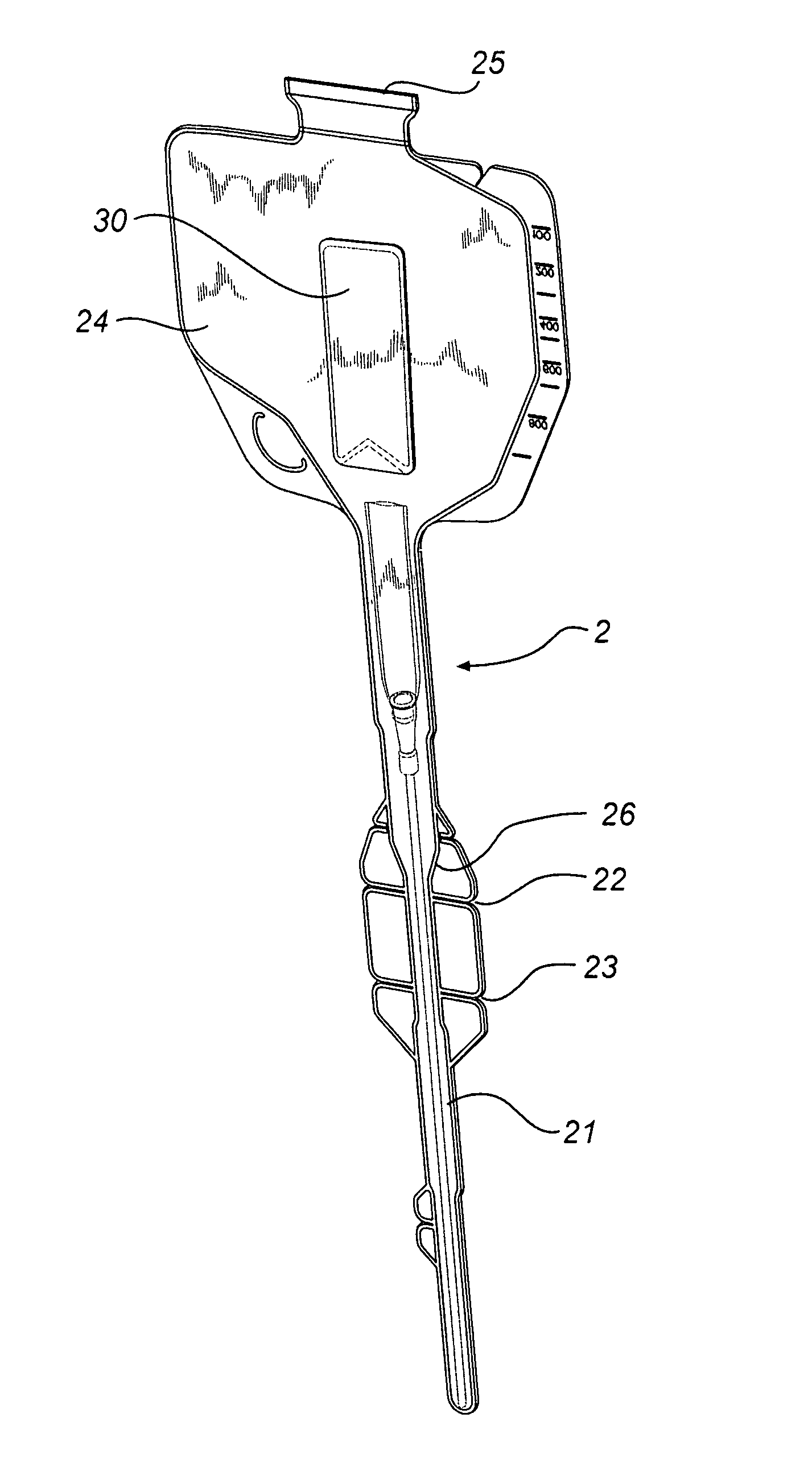
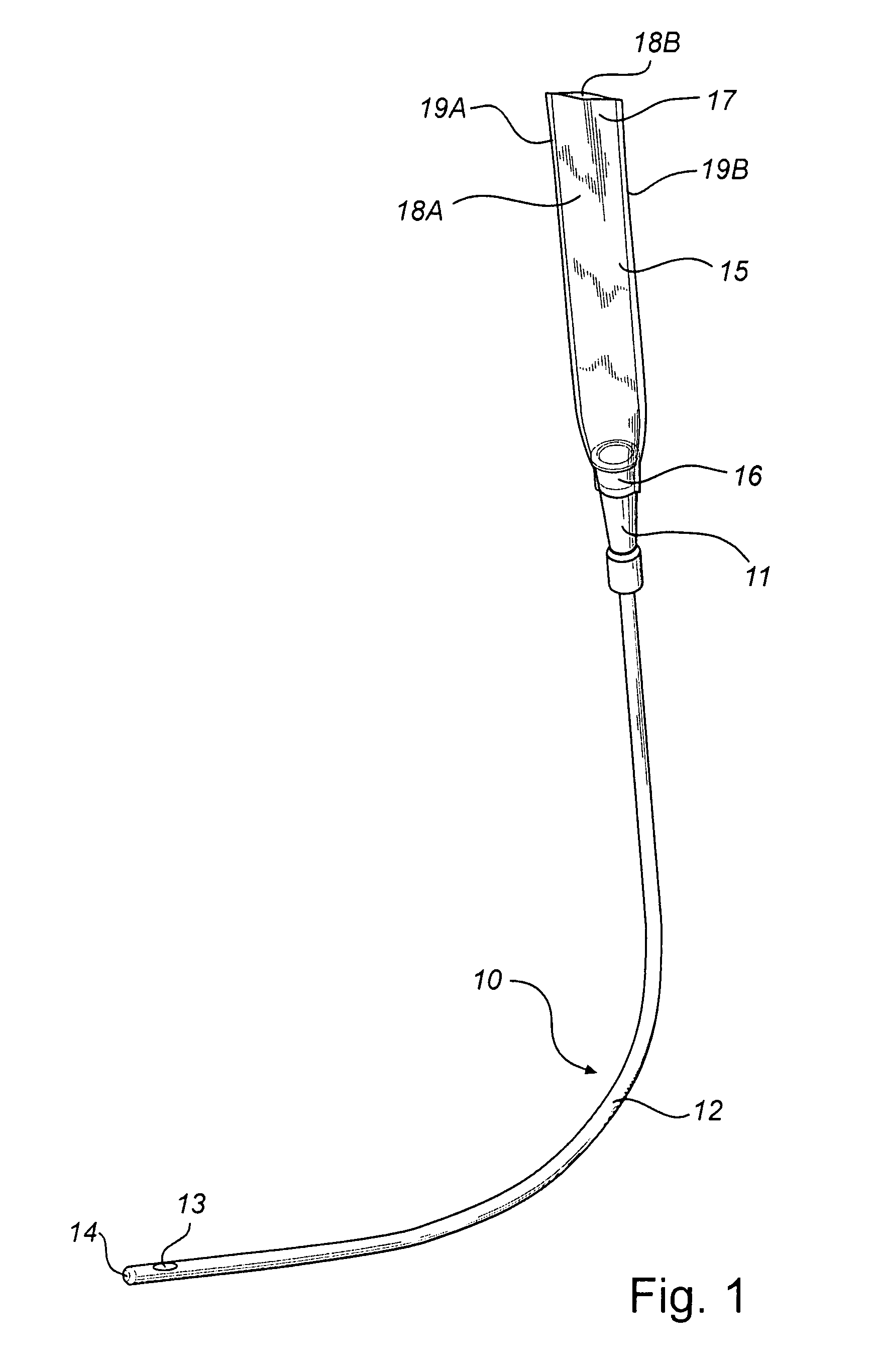
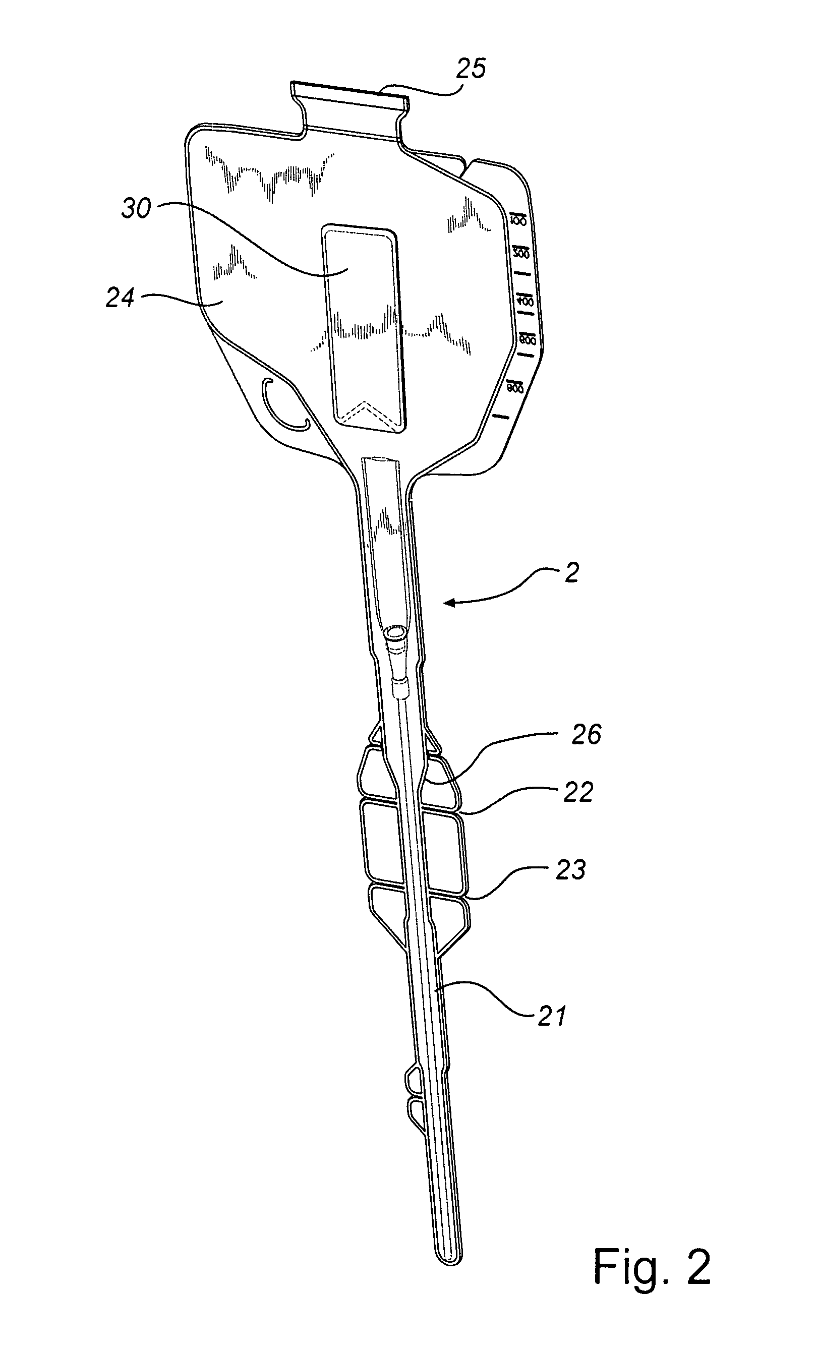
[0047]A catheter 10 as illustrated in the drawings, e.g. in FIG. 1, comprises a flared rearward portion 11 and an elongate shaft or tube 12 projecting forwardly from the rearward portion 11. An open-ended internal lumen (not shown) extends from the rear end of the rearward portion 11 to a drainage aperture 13 in a rounded tip 14 of the elongate tube 12. The rearward portion 11 may function as a connec...


PUM


Abstract

A catheter and catheter assembly are disclosed comprising a urinary catheter comprising an insertion end, a rearward end, and a one way check valve arrangement. The check valve arrangement comprises a tubular part of a flexible material, connected to the rearward end of the catheter and extending past the rearward end in a direction opposite to the insertion end, thereby substantially limiting the flow through the catheter to a single direction from the insertion end to the rearward end. Hereby, a very effective anti-reflux function is achieved, and at the same time the construction is relatively simple and inexpensive, and does not require any essential modifications of the other parts of the urinary catheter.

Description

[0001]This Nonprovisional application claims priority under 35 U.S.C. §119(e) on U.S. Provisional Application No. 60 / 840,465 filed on Aug. 28, 2006, the entire contents of which are hereby incorporated by reference.FIELD OF THE INVENTION[0002]The present invention relates to a urinary catheter, a urinary catheter assembly and a method for producing a urinary catheter.BACKGROUND OF THE INVENTION[0003]Catheters find their use in many different medical applications, such as urinary catheters for bladder drainage. Each catheter is normally pre-packed in a receptacle by the manufacturer, in order to maintain the catheter in a clean and preferably sterile condition.[0004]A urinary catheter in general need to have a lubricant applied to the outer surface thereof to facilitate insertion into the urethra. Especially, for lubrication purposes, a hydrophilic urinary catheter may have a hydrophilic outer surface coating or layer which should be wetted by a fluid such as water for a certain time...

Claims


Application Information

Patent Timeline
Patent Type & Authority Patents(United States)
IPC IPC(8): A61M27/00A61M39/24
CPCA61M25/0017A61M25/002A61M25/0111
Inventor FROJD, GORAN
Owner ASTRA TECH SE
Learn More