Movable body drive method, movable body apparatus, exposure method, exposure apparatus, and device manufacturing method

a technology of movable body and drive method, which is applied in the direction of printers, instruments, program control, etc., can solve the problems of insufficient measurement, inferiority of laser interferometer for mechanical instability, and large overlay budget, and achieve high linear measurement and high measurement reproducibility

Active Publication Date: 2013-07-16
NIKON CORP
View PDF92 Cites 10 Cited by
  • Summary
  • Abstract
  • Description
  • Claims
  • Application Information

AI Technical Summary

Benefits of technology

[0014]According to this method, it becomes possible to linearly drive the movable body at a constant speed quickly and with high precision with respect to the energy beam, as well as drive wafer stage WST precisely to the starting position of the constant speed drive. The former makes it possible to form a pattern on the object with good precision, and the latter makes it possible to improve the overlay accuracy.
[0027]According to this apparatus, at least one of the first movable body and the second movable body holding the mask can be driven according to a predetermined temporal change curve of speed and also along a predetermined path based on the drive signal, while switching between the first detection signal corresponding to a position of the first movable body output by an interferometer system which detects positional information of the first movable body and the second detection signal corresponding to a position of the first movable body output by an encoder system which detects positional information of the first movable body that serves as the drive signal, and it becomes possible to set the first drive period and the second drive period according to their weight.

Problems solved by technology

However, requirements for a stage position control with higher precision are increasing due to finer patterns that accompany higher integration of semiconductor devices, and now, measurement errors resulting from air fluctuation generated by temperature variation of the atmosphere on the beam path of the laser interferometer or by temperature gradient has come to occupy a large percentage in the overlay budget.
However, while the encoder is superior to the laser interferometer in the viewpoint of measurement reproducibility because of using a scale, it is inferior to the laser interferometer for the mechanical instability (drift of the grating pitch, fixed location drift, thermal expansion and the like) of the scale in the viewpoint of linearity.
However, the methods and the like disclosed in these U.S. Patent Application Publication and the like are still not sufficient enough when ensuring a highly accurate and stable position control performance of the stage which is required in the current exposure apparatus.

Method used


Image

  • Movable body drive method, movable body apparatus, exposure method, exposure apparatus, and device manufacturing method
  • Movable body drive method, movable body apparatus, exposure method, exposure apparatus, and device manufacturing method
  • Movable body drive method, movable body apparatus, exposure method, exposure apparatus, and device manufacturing method

Examples


first embodiment

[0044]A first embodiment will be described below, with reference to FIGS. 1 to 13C.

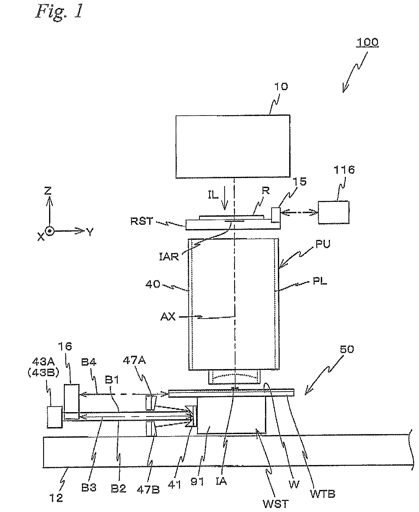
[0045]FIG. 1 schematically shows a configuration of an exposure apparatus 100 related to the first embodiment. Exposure apparatus 100 is a projection exposure apparatus by a step-and-scan method, which is a so-called scanner. As it will be described later on, a projection optical system PL is provided in exposure apparatus 100. In the description below, a direction parallel to an optical axis AX of projection optical system PL will be described as the Z-axis direction, a scanning direction within a plane orthogonal to the Z-axis direction in which a reticle and a wafer are relatively scanned will be described as the Y-axis direction, a direction orthogonal to the Z-axis and the Y-axis will be described as the X-axis direction, and rotational (inclination) directions around the X-axis, the Y-axis, and the Z-axis will be described as θx, θy, and θz directions, respectively.

[0046]Exposure apparatus 100 i...

second embodiment

[0130]Next, a second embodiment will be described. Here, the same reference numerals will be used for the same or similar sections as in the first embodiment previously described, and a detailed description thereabout will be simplified or omitted.

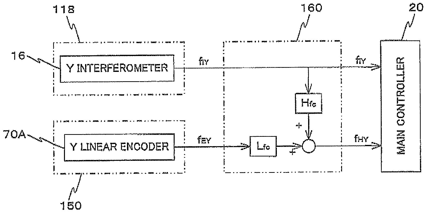
[0131]In the exposure apparatus of the second embodiment, the configuration and the like of the apparatus is the same as exposure apparatus 100 of the first embodiment previously described, except for a part of a stage control system which will be described later on The description below will be focusing on a synchronous drive control of wafer stage WST and reticle stage RST employed in the exposure apparatus of the second embodiment which uses a hybrid method by encoder system 150 and interferometer system 118.

[0132]In the synchronous drive control by the hybrid method in the exposure apparatus of the second embodiment, signal processing device 160 synthesizes (makes) a hybrid signal from an output signal of the interferometer (interferom...


PUM


Abstract

A stage is driven (position control) using a hybrid signal which is obtained by synthesizing an output signal of an interferometer (an interferometer system) and an output signal of an encoder (an encoder system) that are made to pass through a high pass filter and a low pass filter, respectively. A cutoff frequency is set to a frequency corresponding to a speed slightly smaller than the speed of the stage at the time of scanning exposure. This allows the stage to be driven using an interferometer whose linear measurement is high at the time of scanning exposure, and using an encoder whose measurement reproducibility is high at the time of stepping.

Description

CROSS-REFERENCE TO RELATED APPLICATIONS[0001]This non-provisional application claims the benefit of Provisional Application No. 61 / 290,359 filed Dec. 28, 2009, and Provisional Application No. 61 / 302,633 filed Feb. 9, 2010, the disclosures of which are hereby incorporated herein by reference in their entirety.BACKGROUND OF THE INVENTION[0002]1. Field of the Invention[0003]The present invention relates to movable body drive methods, movable body apparatus, exposure methods, exposure apparatus, and device manufacturing methods, and more particularly to a movable body drive method in which a movable body is driven along a predetermined plane, a movable body apparatus including the movable body, an exposure method which uses the movable body drive method, an exposure apparatus which is equipped with the movable body apparatus, and a device manufacturing method which uses the exposure method or the exposure apparatus.[0004]2. Description of the Background Art[0005]Conventionally, in a lit...

Claims


Application Information

Patent Timeline
Patent Type & Authority Patents(United States)
IPC IPC(8): G01B11/00G03B27/58G03B27/32G03B27/42G03B27/62H02K41/02
CPCG03F7/70775G03F7/2049G03F7/2055G05B19/195H01L21/0274
Inventor SHIBAZAKI, YUICHIOKUTOMI, AKIRAHIRANO, KAZUHIRO
Owner NIKON CORP
Why Eureka
Try Eureka