X-ray generator, X-ray imaging apparatus, and control methods therefor
a technology of x-ray generator and x-ray tube, which is applied in the direction of x-ray tube cathode assembly, x-ray tube, application, etc., can solve the problems of low generation efficiency of x-rays and heat generation, and achieve the effect of large current and without reducing the sharpness of an imag
- Summary
- Abstract
- Description
- Claims
- Application Information
AI Technical Summary
Benefits of technology
Problems solved by technology
Method used
Image
Examples
first embodiment
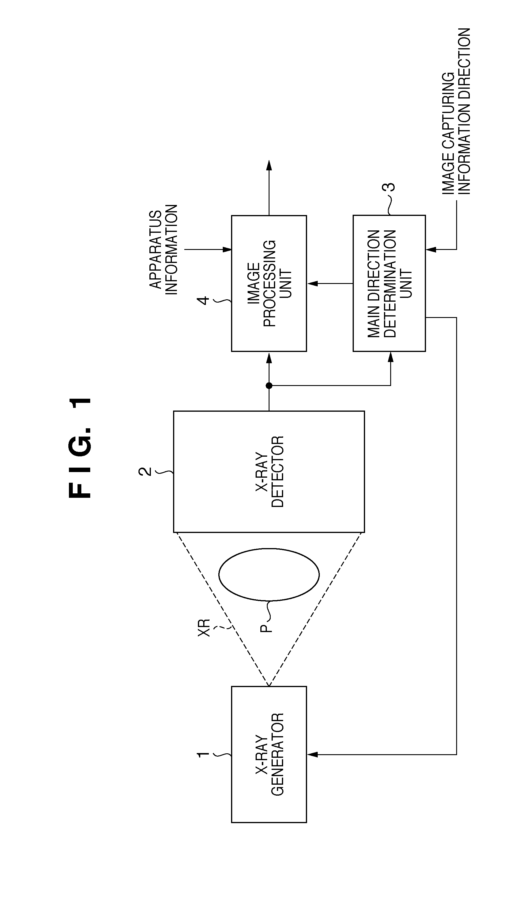
[0029]FIG. 1 is a view showing the arrangement of an X-ray imaging apparatus according to the Referring to FIG. 1, X-rays XR emitted from an X-ray generator 1 are transmitted through an object P to be imaged, and strike an X-ray detector 2. The X-ray detector 2 is a flat panel detector for X-ray images. This detector outputs, as an image, the intensity distribution of X-rays which are transmitted through the object P and attenuated, to a main direction determination unit 3 and an image processing unit 4.
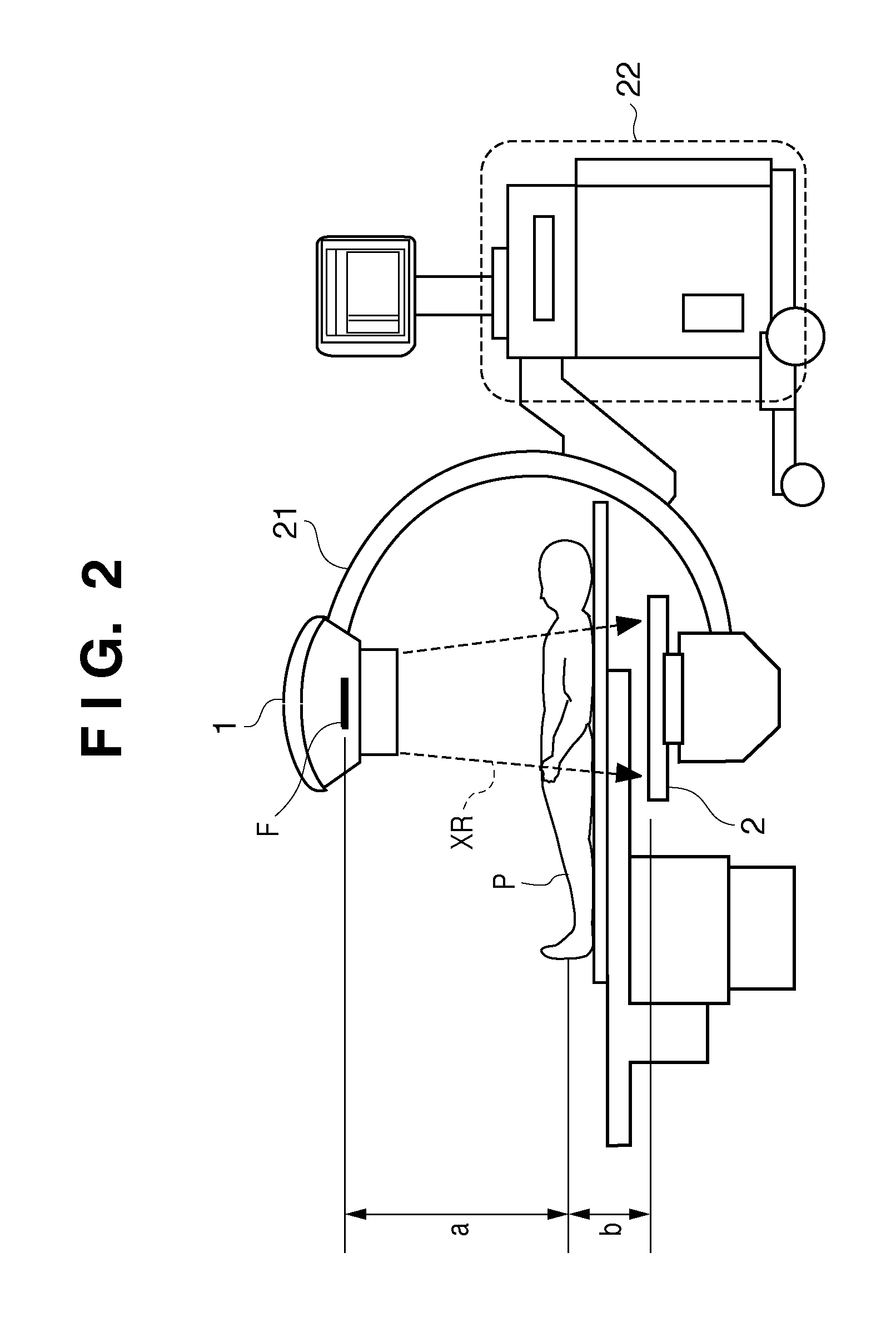
[0030]A fluoroscopic radiography apparatus is a concrete example of such an imaging apparatus. A fluoroscopic radiography apparatus continuously irradiates the object P with X-rays and obtains X-ray images, thereby acquiring a moving X-ray image of the object P. FIG. 2 shows an example of this apparatus, more specifically, a fluoroscopic radiography apparatus which captures a fluoroscopic image of the patient, that is, the object P, by using the X-ray generator 1 and X-ray detector ...
second embodiment
[0056]In the second embodiment, a main direction determination unit 3 inputs image capturing information from the outside in addition to an X-ray image from an X-ray detector 2. In this case, the image capturing information is information about an object to be imaged or information about the main direction of the object. For example, in a medical imaging apparatus, image capturing information includes information indicating a specific region as an object to be imaged, for example, a chest region, extremity region, or abdominal region, information indicating a visual line direction, and information indicating in which direction an object extends on an image when a region to be imaged is an extremity region.
[0057]When the main direction determination unit 3 is implemented as software in a computer as described with reference to FIG. 2, the unit can be configured to allow an operator to directly input image capturing information by using an input device, for example, a keyboard or mous...
third embodiment
[0065]The third embodiment is characterized in that an image processing unit 4 shown in FIG. 1 performs sharpening processing (frequency enhancement processing) for an input X-ray image based on a main direction η determined by a main direction determination unit 3.
[0066]FIG. 7 is a block diagram showing the arrangement of the image processing unit 4. A high-frequency component computing unit 402 receives an X-ray image I input from an X-ray detector 2. A filter selection unit 401 receives the main direction η input from the main direction determination unit 3, and selects a high-frequency component extraction filter corresponding to the main direction. The high-frequency component computing unit 402 extracts a high-frequency component Ih by performing convolution by using the filter selected for the input image I, and outputs the component to an adder 403. The adder 403 adds the input image I and the high-frequency component Ih and outputs a sharpened image Ie.
[0067]The operation o...
PUM
 Abstract
Description
Claims
Application Information
 - R&D
- Intellectual Property
- Life Sciences
- Materials
- Tech Scout
- Unparalleled Data Quality
- Higher Quality Content
- 60% Fewer Hallucinations
Browse by: Latest US Patents, China's latest patents, Technical Efficacy Thesaurus, Application Domain, Technology Topic, Popular Technical Reports.
© 2025 PatSnap. All rights reserved.Legal|Privacy policy|Modern Slavery Act Transparency Statement|Sitemap|About US| Contact US: help@patsnap.com


