Permanent magnet and manufacturing method thereof

Inactive Publication Date: 2013-08-06
NITTO DENKO CORP
View PDF24 Cites 3 Cited by
  • Summary
  • Abstract
  • Description
  • Claims
  • Application Information

AI Technical Summary

Benefits of technology

The present invention relates to a permanent magnet with improved magnetic properties. The technical effect of this patent is that the magnet has higher magnetic properties, including better coercive force and residual magnetic flux density, in comparison to conventional magnets. This is achieved through efficient concentration of V, Mo, Zr, Ta, Ti, W, or Nb in the grain boundaries of the magnet, which prevents grain growth and magnetization reversal. The addition of an organometallic compound, such as an alkyl group, can be easily thermally decomposed during sintering, reducing carbon content in the magnet. Furthermore, by calining the magnet in hydrogen atmosphere, the organometallic compound can be more effectively removed, resulting in a compact body with reduced carbon content. These technical effects enable the magnet to have better performance and consistency.

Problems solved by technology

On the other hand, as to Nd-based magnets such as Nd—Fe—B magnets, poor heat resistance is pointed to as defect.
However, even if the magnet raw material finely milled into a very fine particle size is compacted and sintered, grain growth occurs in the magnet particles at the time of sintering.
Therefore, after sintering, the crystal grain size in the sintered body increases to be larger than the size before sintering, and as a result, it has been impossible to achieve a very fine crystal grain size.
In addition, if the crystal grain has a larger size, the domain walls created in a grain easily move, resulting in drastic decrease of the coercive force.

Method used


Image

  • Permanent magnet and manufacturing method thereof
  • Permanent magnet and manufacturing method thereof
  • Permanent magnet and manufacturing method thereof

Examples


embodiment 1

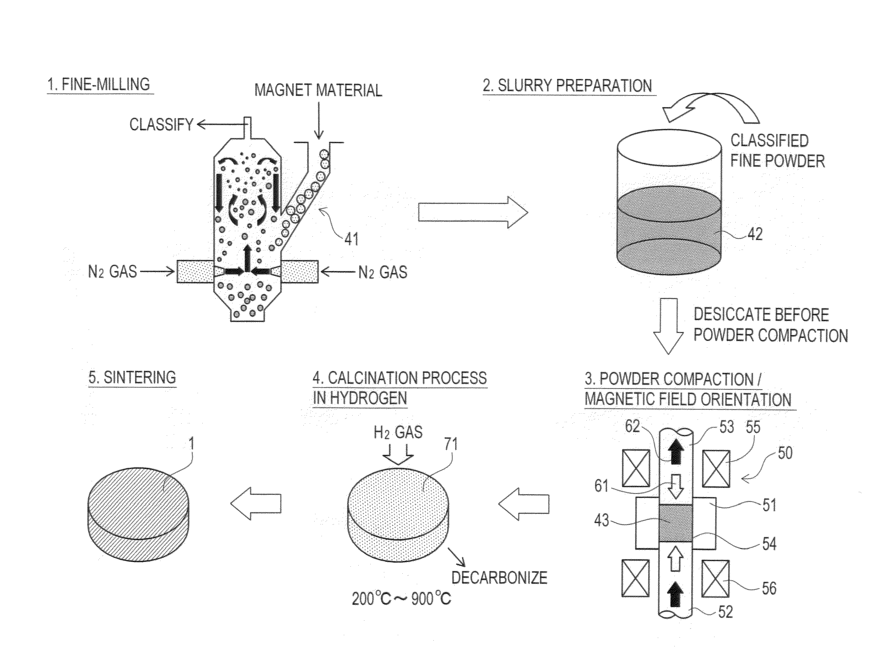
[0088]In comparison with fraction regarding alloy composition of a neodymium magnet according to the stoichiometric composition (Nd: 26.7 wt %, Fe (electrolytic iron): 72.3 wt %, B: 1.0 wt %), proportion of Nd in that of the neodymium magnet powder for the embodiment 1 is set higher, such as Nd / Fe / B=32.7 / 65.96 / 1.34 in wt %, for instance. Further, 5 wt % of niobium n-propoxide has been added as organometallic compound to the milled neodymium magnet powder. A calcination process has been performed by holding a compact body of the magnet powder for five hours in hydrogen atmosphere at 600 degrees Celsius. The hydrogen feed rate during the calcination is 5 L / min. Sintering of the compacted-state calcined body has been performed in the SPS. Other processes are the same as the processes in [First Method for Manufacturing Permanent Magnet] mentioned above.

embodiment 2

[0089]Niobium n-butoxide has been used as organometallic compound to be added. Other conditions are the same as the conditions in embodiment 1.

embodiment 3

[0090]Sintering of a compacted-state calcined body has been performed in the vacuum sintering instead of the SPS. Other conditions are the same as the conditions in embodiment 1.


PUM

PropertyMeasurementUnit
Temperatureaaaaaaaaaa
Grain boundaryaaaaaaaaaa

Abstract

There are provided a permanent magnet and a manufacturing method thereof capable of densely sintering the entirety of the magnet without making a gap between a main phase and a grain boundary phase in the sintered magnet. To fine powder of milled neodymium magnet is added an organometallic compound solution containing an organometallic compound expressed with a structural formula of M-(OR)X (M represents V, Mo, Zr, Ta, Ti, W or Nb, R represents a substituent group consisting of a straight-chain or branched-chain hydrocarbon, X represents an arbitrary integer) so as to uniformly adhere the organometallic compound to particle surfaces of the neodymium magnet powder. Thereafter, a compact body formed through powder compaction is held for several hours in hydrogen atmosphere at 200 through 900 degrees Celsius. Thereafter, through sintering process, a permanent magnet is manufactured.

Description

CROSS REFERENCE TO RELATED APPLICATIONS[0001]This application is a National Stage of International Application No. PCT / JP2011 / 057566 filed Mar. 28, 2011, claiming priority based on Japanese Patent Application No. 2010-082888 filed Mar. 31, 2010, the contents of all of which are incorporated herein by reference in their entirety.TECHNICAL FIELD[0002]The present invention relates to a permanent magnet and manufacturing method thereof.BACKGROUND ART[0003]In recent years, a decrease in size and weight, an increase in power output and an increase in efficiency have been required in a permanent magnet motor used in a hybrid car, a hard disk drive, or the like. To realize such a decrease in size and weight, an increase in power output and an increase in efficiency in the permanent magnet motor mentioned above, film-thinning and a further improvement in magnetic performance are required of a permanent magnet to be buried in the permanent magnet motor. Meanwhile, as permanent magnet, there h...

Claims


Application Information

Patent Timeline
IPC IPC(8): H01F1/057B22F1/16
CPCB22F1/0018B22F1/02H01F41/0266H01F1/0572C22C33/0278B82Y30/00B22F9/023B22F3/10B22F3/02H01F1/0577B22F2999/00B22F2998/10B22F9/04B22F3/101B22F3/087B22F2201/01B22F1/16B22F1/056H01F1/08
Inventor OZEKI, IZUMIKUME, KATSUYAHIRANO, KEISUKEOMURE, TOMOHIROTAIHAKU, KEISUKEOZAKI, TAKASHI
Owner NITTO DENKO CORP
Why Eureka
Try Eureka