Microengineered multipole ion guide

Active Publication Date: 2013-08-13
MICROSAIC SYST
View PDF38 Cites 14 Cited by
  • Summary
  • Abstract
  • Description
  • Claims
  • Application Information

AI Technical Summary

Benefits of technology

[0005]These and other problems are addressed in accordance with the present teaching by providing an ion guide which can be fabricated in accordance with microengineering principles. Accordingly, a first embodiment of the application provides a microengineered mass spectrometer system comprising an ion guide chamber comprising a plurality of rods defining an ion guide, a first set of rods being supported on a first substrate and a second set of rods being supported on a second substrate, and an analyser chamber comprising a mass analyser, wherein the ion guide is operable for directing ions towards the analyser chamber and the supported rods are circumferentially arranged about an ion beam axis, as detailed in claim 1. Advantageous embodiments are provided in the dependent claims.

Problems solved by technology

However, as the field radius decreases, and / or the number of rods used to define the multipole increases, problems associated with such conventional techniques include the provision of a secure and accurate mounting arrangement with independent electrical connections.

Method used


Image

  • Microengineered multipole ion guide
  • Microengineered multipole ion guide
  • Microengineered multipole ion guide

Examples


Embodiment Construction

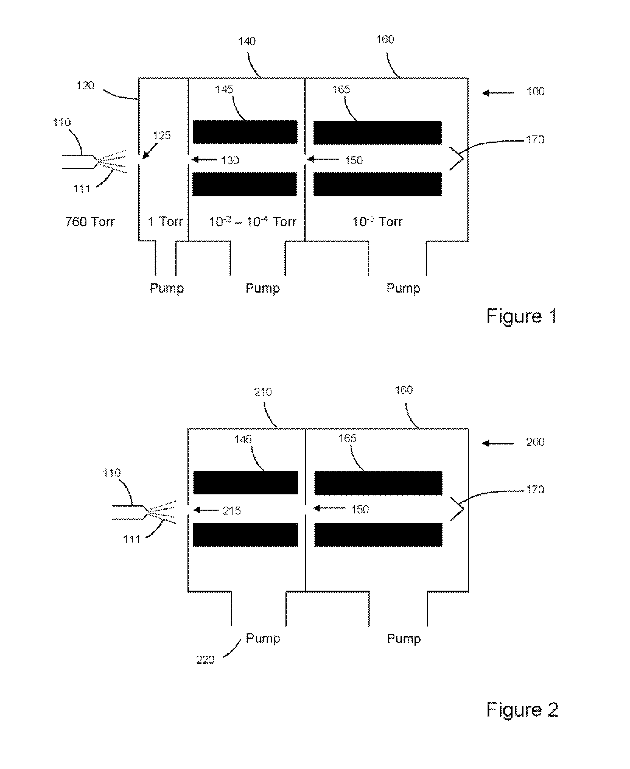
[0019]FIG. 1 shows in schematic form an example of a mass spectrometer system 100 in accordance with the present teaching. An ion source 110, such as an electrospray ion source, effects generation of ions 111 at atmospheric pressure. In this exemplary arrangement, the ions are directed into a first chamber 120 through a first orifice 125. The pressure in this first chamber is of the order of 1 Torr. A portion of the gas and entrained ions that passes into the first chamber 120 through orifice 125 is sampled by a second orifice 130 and passes into a second chamber 140, which is typically operated at a pressure of 10−4 to 10−2 Torr. The second orifice 130 may be presented as an aperture in a flat plate or a cone. Alternatively, a skimmer may be provided proximal to or integrated with the entrance to the second chamber so as to intercept the initial free jet expansion. The second chamber, or ion guide chamber, 140 is coupled via a third orifice 150 to an analysis chamber 160, where the...


PUM


Abstract

A microengineered multipole ion guide for use in miniature mass spectrometer systems is described. Exemplary methods of mounting rods in hexapole, octupole, and other multipole geometries are described. The rods forming the ion guide are supported in etched silicon structures defined in at least first and second substrates.

Description

CROSS-REFERENCE TO RELATED APPLICATIONS[0001]This application claims the benefit of Great Britain Patent Application No. GB1005551.5 filed on Apr. 1, 2010.TECHNICAL FIELD OF THE INVENTION[0002]The present application relates to ion guides. The invention more particularly relates to a multipole ion guide that is microengineered and used in mass spectrometer systems as a means of confining the trajectories of ions as they transit an intermediate vacuum stage. Such an intermediate vacuum stage may typically be provided between an atmospheric pressure ion source (e.g. an electrospray ion source) and a mass analyser in high vacuum.BACKGROUND OF THE INVENTION[0003]Atmospheric pressure ionisation techniques such as electrospray and chemical ionisation are used to generate ions for analysis by mass spectrometers. Ions created at atmospheric pressure are generally transferred to high vacuum for mass analysis using one or more stages of differential pumping. These intermediate stages are used...

Claims


Application Information

Patent Timeline
Patent Type & Authority Patents(United States)
IPC IPC(8): H01J49/26
CPCH01J49/063H01J49/0018H01J49/421H01J49/4225
Inventor WRIGHT, STEVENO'PREY, SHANE MARTIN
Owner MICROSAIC SYST
Why Eureka
Try Eureka